4
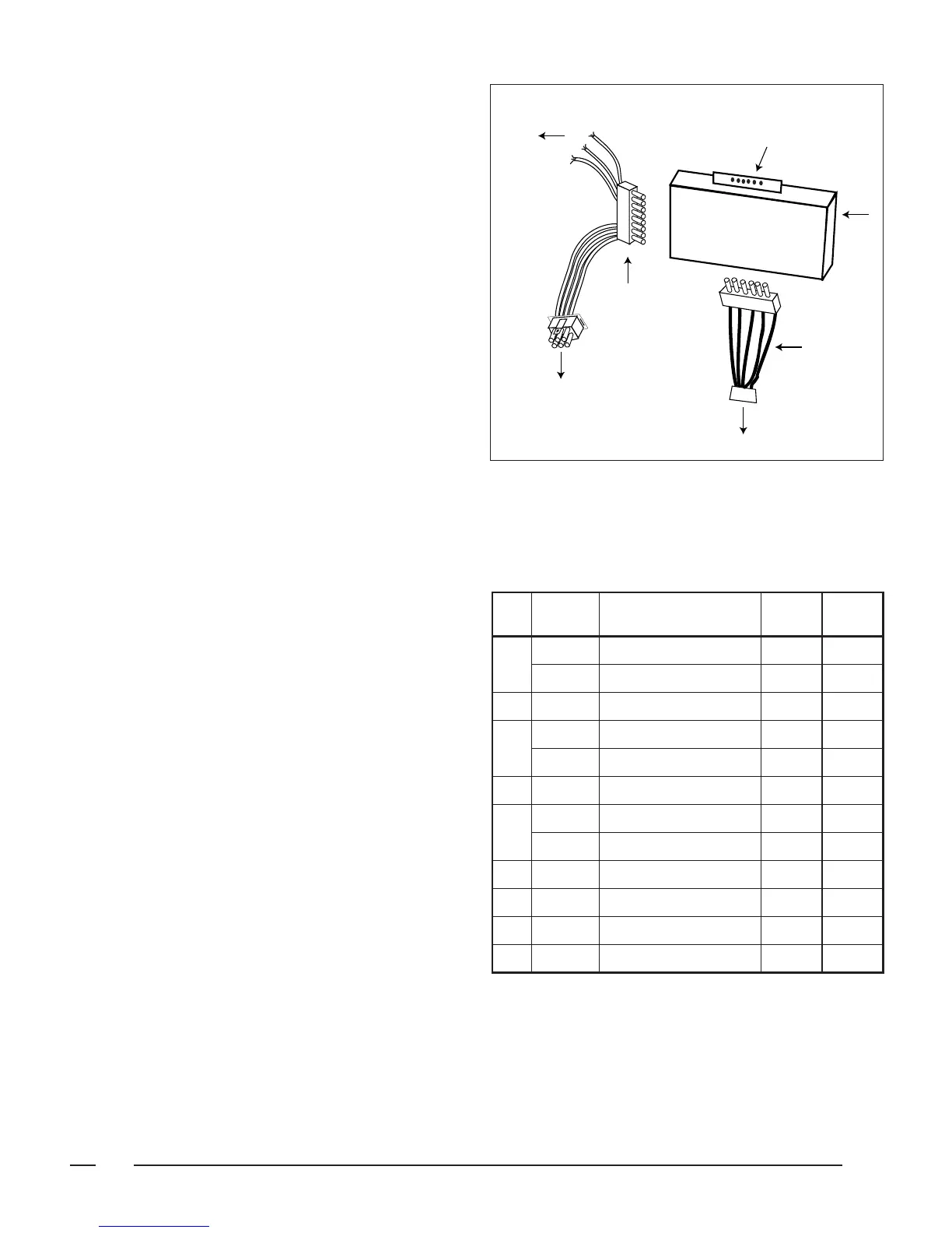
Figure 4. Relay Box Connection
Low Voltage Wiring
5-Wire
Harness
6-Wire
Harness
Connect to Blower Plug
Connect to
Furnace
Control
Panel
Wire Nut to
Furnace
Thermostat
Wires
(Red to Red;
Yellow to
Yellow (or
Grey);
White to
White)
Relay
Box
Blower & Relay Replacement
Parts List
Find the 4-wire harness supplied with the relay box.
Connect its 6 circuit matrix connector to the blower plug
and connect its 6 circuit in-line connector to the bottom
of the relay box (see Figure 4).
6. Bring in the low voltage fi eld wires from the thermostat
and air-conditioning or heat pump unit and attach them
to the low voltage screw terminals protruding from the
top of the relay box (see Figure 4). See Figure 7 for
System Wiring.
7. Turn on the power to the furnace. Replace the furnace
door. The unit is now ready for operation.
SYSTEM OPERATION —
For the AC/Heat Pump Relay Box
HEATING: Set the furnace fan switch to AUTO, the ther-
mostat system switch to HEAT, and the thermostat fan
switch to AUTO.
COOLING: Set the furnace fan switch to AUTO, the ther-
mostat system switch to COOL, and the thermostat fan
switch to AUTO.
EMERGENCY HEAT: (Used with a heat pump only.) Set
the furnace fan switch to AUTO, the thermostat system
switch to EMERGENCY HEAT, and the thermostat fan
switch to AUTO.
CONTINUOUS AIR CIRCULATION: Set the thermostat
fan switch to ON.
SHUT OFF SYSTEM: Set the thermostat system switch to
OFF and set it to the lowest temperature setting. Set
the furnace system switch to OFF and shut off all power
to the air conditioner.
For the 2-Wire Relay Box
HEATING: Set the furnace fan switch to AUTO, the tem-
perature switch (on the relay box) to HEAT, and the
fan switch (on the relay box) to AUTO.
COOLING: Set the furnace fan switch to AUTO, the tem-
perature switch (on the relay box) to COOL, and the
fan switch (on the relay box) to AUTO.
CONTINUOUS AIR CIRCULATION: Set the fan switch
(on the relay box) to ON.
SHUT OFF SYSTEM: Set the system switch (on the relay
box) to OFF and set the thermostat to the lowest tem-
perature setting. Set the furnace system switch to OFF
and shut off all power to the air conditioner.
ITEM
# PART # DESCRIPTION 903092A 902898A
1
375952 Cover (2 Wire) 1
376430 Cover (AC/HP) 1
2 378700 Box, Relay 1 1
3
624567 2 Wire Relay Circuit Board 1
624568 AC/HP Relay Circuit Board 1
4 260300 Wire Harness 1 1
5
378690 Mounting Bracket- Left 1
376050 Mounting Bracket 1
6 669084 Bezel 1
7 632278 Switch Cap 2
8 266660 Wiring Harness Blower 1 1
9 378680 Mounting Bracket- Right 1
 Loading...