EasyManua.ls Logo

Nordyne R6GD-X36C072 - User Manual

Nordyne R6GD-X36C072
28 pages
Print Icon
To Next Page IconTo Next Page
Loading...
Installation Instructions
Single Package Gas Heating/Electric Cooling
3 Phase
Do not store or use gasoline
or other fl ammable vapors
and liquids in the vicinity of
this or any other appliance.
DO NOT DESTROY. PLEASE READ CAREFULLY AND KEEP IN A SAFE PLACE FOR FUTURE REFERENCE.
WARNING:
Improper installation, ad-
justment, alteration, service,
or maintenance can cause
injury or property damage.
Refer to this manual. For as-
sistance or additional infor-
mation consult a qualifi ed
installer, service agency, or
the gas supplier.
These instructions are primarily intended to assist qualifi ed individuals experienced in the proper installation of this
appliance. Some local codes require licensed installation/service personnel for this type of equipment. Read all
instructions carefully before starting the installation.
FOR YOUR SAFETY
WHAT TO DO IF YOU SMELL GAS
Do not try to light any appli-
ance.
Do not touch any electrical
switch; do not use any phone
in your building.
Immediately call your gas sup-
plier from a neighbor’s phone.
Follow the gas supplier’s
instructions.
If you cannot reach your gas
supplier, call the fi re depart-
ment.
Extinguish any open fl ame.
High Effi ciency
FOR YOUR SAFETY
!
T
M

Table of Contents

Question and Answer IconNeed help?

Do you have a question about the Nordyne R6GD-X36C072 and is the answer not in the manual?

Overview

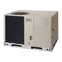
This document provides installation and maintenance instructions for a Single Package Gas Heating/Electric Cooling unit, designed for outdoor rooftop or ground-level slab installations. These units are shipped ready for horizontal duct connections and can be easily converted for downflow connections.

Function Description

The device is a packaged gas heating/electric cooling unit, meaning it combines both heating and cooling functions in a single outdoor unit. It operates on a three-phase electrical supply. The unit utilizes R-410A refrigerant for its cooling cycle.

Key components and their functions include:

  • Blower: A multispeed fixed torque variable speed blower circulates air through the system. The blower speeds are factory preset but can be adjusted for optimum system performance and comfort.
  • Gas Valve: Controls the flow of gas to the burners, opening automatically and regulating gas pressure when energized.
  • Burners: These are ignited automatically by an ignition device. The burner flame is designed to carry over immediately between all burners, appearing blue without yellow tips, and extending from each burner without lifting off, curling, or floating.
  • Heat Exchanger: Transfers heat from the combustion gases to the circulating air.
  • Flame Sensor: Proves that flame has carried over from the ignitor to the right-most burner. If no flame is sensed, the unit shuts down automatically.
  • Flame Roll-Out Control: Verifies that the burner flame is being drawn into the heat exchanger tubes. If the flame is not drawn in, this control opens, turning off the gas supply to the burners. It is a manually re-settable device.
  • Pressure Switch: Verifies that the inducer motor is drawing combustion gases through the heat exchanger tubes and venting them through the vent system.
  • Over-Temperature Limit Control: Prevents the air temperature leaving the unit from exceeding the maximum outlet air temperature. If this limit opens, the integrated control diagnostic will flash, and the circulating air blower and combustion blower will continue to operate.
  • Vent Cover Assembly: An integral venting system is provided, and the vent cover assembly must be installed over the vent outlet on the exterior corner panel to ensure proper operation.
  • Condensate Drain: Removes condensate from the unit through a 3/4" female pipe fitting. A 2-inch deep condensate trap must be installed in the drain line and primed with water.
  • Thermostat: A single-stage cooling/single-stage heating 24VAC thermostat is used to control the unit. A two-stage cooling/single-stage heating thermostat is recommended for economizer operation.

Usage Features

  • Installation: Designed for outdoor use, either on a concrete mounting pad at ground level or on a roof curb for rooftop installations. Proper clearances to combustible materials and for service access must be maintained.
  • Ductwork: The unit is shipped for horizontal duct connections but can be converted for downflow. Ductwork should be sized according to ACCA Manual D and properly insulated if passing through unconditioned spaces.
  • Air Filtration: A suitable air filter system must be installed in the unit or in the return air system upstream of the evaporator coil. The unit should never be operated without a filter. Internal filter racks are provided for specific models, and filters should be replaced with the same dimensional size.
  • Gas Supply: The unit is equipped for natural gas but can be converted to LP/propane gas using a special kit. Gas piping must comply with local codes, and a 1/8 inch NPT plugged tap must be installed upstream of the gas supply connection for pressure measurement. The firing rate must be verified and adjusted by modifying the gas manifold pressure.
  • Electrical Wiring: All electrical wiring must comply with local and national codes. The unit is factory wired for 240V transformer operation but can be converted to 208V. A separate branch electrical circuit and proper grounding are required.
  • Thermostat Operation: The thermostat controls the system's cooling, heating, and fan-only modes. In cooling mode, the blower, compressor, and outdoor fan energize. In heating mode, the inducer blower starts, followed by igniter warm-up and gas valve opening, with flame proving by the flame sensor. The control includes an adaptive ignition feature. In fan-only mode, the circulating blower runs at a selected speed.
  • Safety Features: The flame roll-out control and over-temperature limit control are critical safety devices. The flame roll-out control is manually re-settable, and neither it nor the over-temperature limit control should be bypassed. The unit also includes a 3-amp fuse for low voltage protection.
  • Diagnostic Codes: The unit features status lights (red and yellow) that flash in specific patterns to indicate fault conditions, aiding in troubleshooting.

Maintenance Features

  • Routine Maintenance: Proper maintenance is crucial for optimum performance. This includes inspecting and cleaning or replacing the air filter every three to four weeks.
  • Air Filter: Filters should be regularly inspected and cleaned or replaced to prevent dust and lint buildup, which can lead to efficiency loss, equipment damage, and fire risk.
  • Vent Cover Assembly: The screen of the vent cover assembly should be inspected and cleaned at the beginning of each heating and cooling season.
  • Condensate Drain and Outdoor Coil: These components should be inspected and cleaned at the beginning of each cooling season, removing any debris and cleaning the outdoor coil and hail guard louvers with mild detergent and water.
  • Electrical Connections: Electrical connections should be inspected for tightness at the beginning of each heating and cooling season.
  • Motor Lubrication: The motors for the circulating air blower, outdoor fan, and combustion blower are pre-lubricated at the factory and do not require further oiling.
  • Blower Compartment: The blower compartment should be cleaned monthly during heating and cooling seasons to remove dirt and lint that can accumulate on the blower and motor, preventing excessive loads and shortened service life.
  • Heat Exchanger and Burner Maintenance: The heat exchanger, vent system, and burners should be inspected and cleaned annually by a qualified serviceman to ensure continued safe operation and identify deterioration from corrosion. Cleaning involves removing the combustion blower, collector pan, and burner assembly, then using a wire brush and vacuum cleaner to clean the heat exchanger tubes and burners. Extreme care must be taken not to damage the ignitor during cleaning.
  • Refrigerant Charging: The units are factory-charged with R-410A. Refrigerant charge can be checked and adjusted through service ports, but this should only be done by qualified, trained personnel familiar with safe and environmentally responsible refrigerant handling procedures.
  • Safety Precautions: Always disconnect all electrical power to the unit before performing any maintenance or service. Use caution when removing parts due to sharp metal edges.
  • Documentation: The manual emphasizes the importance of reading all instructions carefully, following local and national codes, and consulting qualified personnel for assistance or service. The homeowner's information manual should be reviewed with the homeowner, and the literature package left with them.

Nordyne R6GD-X36C072 Specifications

General IconGeneral
SEER Rating14
HSPF Rating8.2
Voltage208/230V
Phase1
Refrigerant TypeR-410A
Cooling Capacity36000 BTU/h