Heat Exchanger Replacement Procedure
Diagram
Page 7
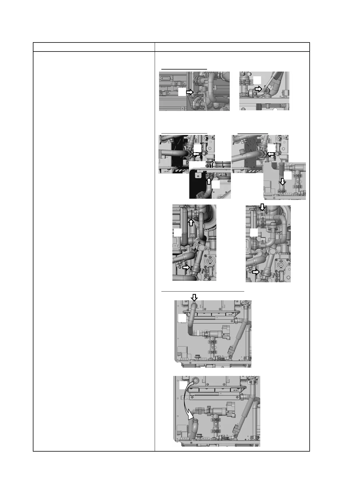
(5) Tilt Pipe - Water Servo - Main
to the bottom of the unit.
(4) Remove "C" Clamp,
Pipe - Primary SS HEX Connection.
Pipe - Primary SS HEX to T-Elbow.
(3) Remove 2 "C" Clamps,
○EZ111DV/EZ98DV & NCC199CDV
(2) Remove 2 "C" Clamps,
Pipe - T-Elbow to Outlet Water Connection.
○NCC199CDV ONLY
(1) Remove 2 "C" Clamps,
Pipe - Primary SS HEX to Drain Water Connection.
Procedure
5. Remove Pipes for EZ111DV/EZ98DV or NCC199CDV
(Refer to page 8 for NRCB199DV/NRCB180DV.)
NCC199CDV ONLY
(1)
(1)
(2)(2)
(2)
(2)
(3)(3)
EZ111DV / EZ98DV &
(4)
(5)