DE
EN
NL
FR
DA
SV
EN
DE
SWIMMING POOL HEAT PUMP TYPE PXSWIMMING POOL HEAT PUMP TYPE PX
22
23
Alterations which serve the technological progress as well as errors excepted! ORIGINAL MANUAL NORSUPWWW.NORSUP.EU Alterations which serve the technological progress as well as errors excepted!
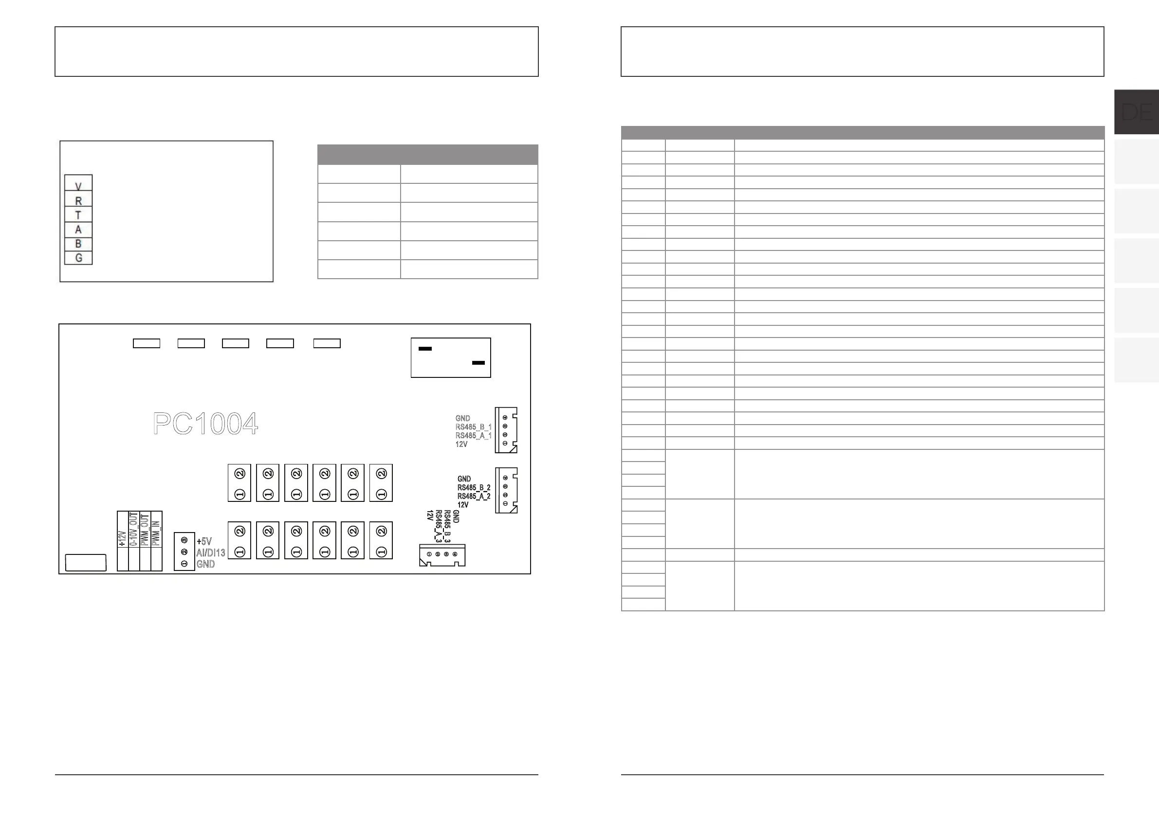
4.4 INTERFACE DRAW IN
(1) Wire control interface diagram and definition
Sign Meaning
V 12V (power +)
R No use
T No use
A 485A
B 485B
G GND (power-)
(2) Controller interface diagram and definition
Main board of the input and output interface instructions below
4.OPERATION AND USE
23
Sign
Meaning
V
12V(power +)
R
No use
T
No use
A
485A
B
485B
G
GND(power-)
V
R
T
A
B
G
(2) Parameter list
Meaning
Default Remarks
Refrigeration target temperature set point
27
℃
Adjustable
Heating the target temperature set point
27
℃
Adjustable
Automatic target temerature set point
27
℃
Adjustable
4.4
Interface drawin
(1) Wire control interface diagram and definition
(2) Controller interface diagram and definition
AC-L
OUT1
OUT2
CN2
CN8
CN13
OUT3
AC-N
OUT4
OUT5
PC1004
CN9
GND
GND
GND
GND
GND
GND
GND
GND
GND
GND
GND
GND
AI/DI12
AI/DI11
AI/DI10
AI/DI09
AI/DI08
AI/DI07
AI/DI06
AI/DI05
AI/DI04
AI/DI03
AI/DI02
AI/DI01
0-10V_OUT
PWM_OUT
PWM_IN
+12V
GND
GND
GND
GND
+5V
AI/DI13
GND
GND
RS485_B_2
RS485_A_2
12V
G
N
D
R
S
4
85
_
B
_
3
R
S
48
5
_A_
3
12
V
GND
RS485_B_1
RS485_A_1
12V
Number Sign Meaning
01 OUT1 Compressor (output 220-230VAC)
02 OUT2 Water pump (output 220-230VAC)
03 OUT3 4-way valve (output 220-230VAC)
04 OUT4 High speed of fan (output 220-230VAC)
05 OUT5 Low speed of fan (output 220-230VAC)
06 AC-L Live wire (input 220-230VAC)
07 AC-N Neutral wire (input 220-230VAC)
08 AI/DI01 Emergency switch input
09 AI/DI02 Water flow switch input
10 AI/DI03 System low pressure input
11 AI/DI04 System high pressure input
12 AI/DI05 System suction temperature input
13 AI/DI06 Water input temperature input
14 AI/DI07 Water output temperature (input)
15 AI/DI08 System fan coil temperatureinput
16 AI/DI09 Ambient temperature input
17 AI/DI10 Mode switch input
18 AI/DI11 Master-slave machine switch / Antifreeze temperature input
19 AI12(50K) System Exhaust temperature input
20 0_5V_IN Compressor current detection/Pressure sensor (input)
21 PWM_IN Master-slave machine switch / Feedback signal of EC fan (input)
22 PWM_OUT AC fan control (output)
23 0_10V_OUT EC fan control (output)
24 +5V +5V (output)
25 +12V +12V (output)
26 GND
27 485_B1
Frequency conversion board communications
28 485_A1
29 12V
30 GND
31 485_B2
Color line controller communication
32 485_A2
33 12V
34 CN9 Electronic expansion valve
35 GND
36 485_B3
The port for centralized control system
37 485_A3
38 12V