Installation Manual
(For a single or dual gate installation)
Horizontal Support
Gate Swings Evenly and Freely
Hung Firmly and Plumb
Post Bracket
Control Box
Fence Post Set in Concrete Fence Post Set in Concrete
Run 1000' (max.) of low
voltage wire to control
box from transformer
Power Cable
PVC conduit (not included)
to protect wire from lawn
mowers and weed eaters.
PVC conduit (not included)
to run second opener power
cable under driveway.
Gate Bracket
Warning Sign
Secondary Opener
Primary Gate Opener
Horizontal Support
Post Bracket
Gate Bracket
Warning Sign
120 Volt indoor
Transformer
(surge protector
not supplied)
12 Volt automotive or marine
type battery in weather proof
housing (not included).
Example of Dual Gate nished installation
(Installations vary slightly on different types of gates)
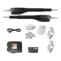
MM371W
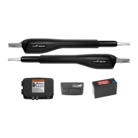
MM372W
Single gate installation [MM371W]
Dual gate installation [MM372W]
This product meets the requirements of UL325, the standard for gate operator safety.
Mighty Mule® is the retail brand of Nortek Security & Control, LLC