Do you have a question about the Nortek Control Mighty Mule MM571W and is the answer not in the manual?
Key safety rules for operators and users to prevent injury or death.
Safety precautions during installation, including zones, signs, and obstruction detection.
Step-by-step guide for mounting the operator arm for pull-to-open gates.
Step-by-step guide for mounting the operator arm for push-to-open gates.
Configuring DIP switches, programming transmitters, and setting gate limits.
Guides to diagnose and resolve issues based on audible feedback, visual indicators, and common problems.
| Weight Capacity | 850 lbs |
|---|---|
| Gate Length (Max) | 18 ft |
| Battery Backup | Yes |
| Weather Resistant | Yes |
| Solar Compatible | Yes |
| Remote Control | Yes |
| Number of Remotes Included | 2 |
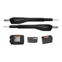
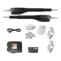
| Type | Automatic Gate Opener |
| Gate Type | Swing Gate |
| Smart Control | Yes |
| Connectivity | Wi-Fi |
| Motor Type | DC |
| Safety Features | Auto-reverse |
| Warranty | 1 year |