- 1 -
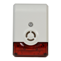
Siren / Strobe
LED
INDICATOR
SIREN
SOUNDER
STROBE
LIGHTS
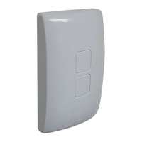
MOUNTING
PLATE
LOCKING
TAB
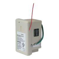
BATTERY
HOLDER
PROGRAM
/ TAMPER
SWITCH
PRESS TO
UNLATCH
NOTE: This unit must be “included in the Network” only where it will be permanently installed. The proper operation of this node in the
mesh network is dependent on it knowing its location with respect to other nodes. You cannot “test bench” confi gure this module, then install.
WIRELESS SIREN / STROBE
The GoControl family of Z-Wave™ certifi ed wireless Security devices (siren/
strobe, motion sensor, and door/window sensor) bring a new level of intelligent
wireless capability to commercial and residential environments.
The Z-Wave wireless protocol is an international wireless standard for remote
home automation, security and other applications. Embedded in each device,
the Z-Wave smart chip enables two-way RF communication among hundreds
of Z-Wave enabled devices, allowing products and services from multiple
manufacturers to work seamlessly.
GoControl Z-Wave products are easy to install, and create an integrated
wireless network with nearly limitless expansion and interoperability with
security and health monitoring systems, energy management, home
entertainment, appliances, and more.
The siren/strobe will sound a loud siren and fl ash a bright strobe when activated
by the Z-Wave™ Controller.
For indoor use only. Retain instructions for future use.
INSTALLATION
1. Remove the mounting bracket by pressing on the locking tab and sliding the bracket
downward from the siren/strobe.
2. Use a Phillips screwdriver to remove the two battery compartment cover screws and
lift off the battery compartment cover.
3. Remove the battery holder. OBSERVING POLARITY, install 4 Type “AA” Alkaline
batteries into the battery holder.
4. Fit the battery holder into the unit and secure the battery compartment cover with
the two screws.
For “Inclusion” to (adding to) a network:
Refer to your Controller operating instructions to add the siren/strobe under the
command of the Wireless Controller.
1. Prepare the Controller to include a unit to the network by adding it to a group (method
of adding a node to the network). Refer to the Controller instructions.
2. If your Controller supports Network Wide Inclusion (NWI) locate the siren/strobe near
the proposed installation location. If not, skip to Step 5.
3. With your Controller in Inclusion mode, press the siren/strobe Program/Tamper
switch for 1 second and release. The LED will blink.
4. You should see an indication on your Controller that the “device was included” in the
network. The LED will stop blinking. Skip to Step 8.
If the LED does not stop blinking, relocate the siren/strobe to within 100 feet (line of
sight) of a Z-Wave device or your hub and repeat Step 3. If the LED continues to blink,
your Controller does not support NWI, continue with Step 5.
5. Place the siren/strobe within 3 feet of the Controller.
6. With your Controller in Inclusion mode, depress the siren/strobe Program/Tamper
switch for 1 second then release. The LED will blink.
7. You should see an indication on your Controller that the “device was included” in the
network. The LED will stop blinking.
8. The device will appear in the list of Switches. It should display “binary switch”.
✓ NOTE: If you have trouble adding the siren/strobe to a group it may be that the Home
ID and Node ID were not cleared from it after testing. You must fi rst “RESET UNIT”
with your Controller to remove it from the network. Although adding it to a group
includes it in the network, removing it from a group does not remove it from the
network. “RESET UNIT” removes it completely from the network.
For “Exclusion” from (removing from) a network:
1. Set up the Z-Wave™ Interface Controller into “exclusion” mode, and following its
instruction to delete the siren/strobe from the controller.
2. Press the siren/strobe Program/Tamper switch for 1 second and release to be
excluded. The LED light will fl ash continuously when the sensor is in the Exclusion
condition.
Mounting
1. Using the two mounting screws or adhesive tape, affi x the mounting bracket at the
chosen location. The locking tab points down.
2. Slide the siren/strobe onto the mounting bracket until the locking tab snaps into place.
PRINTER’S INSTRUCTIONS:
INSTR, INSTL, WA105DBZ, GO CONTROL; P/N: 10004403 X3; INK: BLACK; MATERIAL: 20# MEAD BOND; SIZE: 8.500” x 11.000”; TOLERANCE: ± .125”; SCALE: 1-1; PAGE 1 OF 2
TM
OBSERVE
BATTERY
POILARITY !!!
INSERT
4 TYPE "AA"
ALKALINE
BATTERIES IN
IN HOLDER
Battery Installation