EasyManua.ls Logo

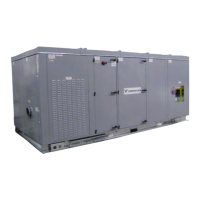
Nortek VENMARCES VHC-50 User Manual

Nortek VENMARCES VHC-50
93 pages
To Next Page IconTo Next Page
Page #1 background imageLoading...
Page #1 background image
VHC
Energy Recovery Ventilators with Enthalpy Wheels and
Integrated Heating and Cooling
Installation, Operation and Maintenance Instructions Manual
Capacity: 800 to 5,500 cfm
Model: VHC-36, VHC-42, VHC-50
IMPORTANT
The use of this appendix is specifically intended for a
qualified installation and service agency. A qualified in-
stallation and service agency must perform all installation
and service of these appliances.
FOR YOUR SAFETY
What to do if you smell gas:
1. Open windows if appliance is indoors.
2. Do not touch electrical switches or use any phone
in the building.
3. Extinguish any open flame.
4. Leave the building immediately.
5. Immediately call Gas Supplier.
WARNING
Improper installation, adjustment, alteration, service or
maintenance can cause injury or death. Read the instal-
lation, operation and maintenance instructions thor-
oughly before installing or servicing this equipment.
Table of Contents

Questions and Answers:

Nortek VENMARCES VHC-50 Specifications

General IconGeneral
BrandNortek
ModelVENMARCES VHC-50
CategoryHeating System
LanguageEnglish

Summary

Safety Considerations

Installation

Electrical Connections

Power Supply

Details primary electrical power connection requirements and procedures for the unit.

Field Connection

Explains how to make field wiring connections for power and controls to the unit.

Coil or Water Source Heat Pump (WSHP) Piping Connections

Refrigeration Systems

Compressors

Information on compressor types and maintenance requirements.

Condenser

Details on air-cooled and water-cooled condenser types and cleaning.

Start-up

Pre Start-up Procedure

Lists checks to perform before initiating unit start-up.

Start-up Procedure

Provides a step-by-step guide for unit start-up and initial operation.

Frost Control

Variable Speed Drive Frost Prevention

Explains VSD-based frost prevention for continuous ventilation.

Non-defrost

Outlines conditions where frost control is not required.

Frost Control Options with Recirculation

Discusses the interaction of frost control and recirculation options.

Airflow Balancing

Maintenance

Fans

Forward Curved Supply or Exhaust Fan and Motor

Details the removal and installation of fan and motor assemblies.

Enthalpy Wheel

Coils

Refrigerant Systems

Evaporator Section

Description of the direct expansion coil and its components.

Components of a Direct Expansion System

Overview of the direct expansion system, including the TXV.

System Operation Check

Appendix F: Electrical Data

Appendix G: Standard Field Wiring Terminals

Control Field Wiring

Details low voltage terminal control wiring for electro-mechanical units.

Appendix H: Terminal Control Diagrams

Occupied Ventilation

Explains terminal connections for occupied ventilation control.

Occupied Timer Sensor

Describes terminal connections for occupied timer sensor control.

Unoccupied Recirculation

Details terminal connections for unoccupied recirculation control.

VFD High Speed Control

Explains VFD control connections for high-speed fan operation.

CO2 Ventilation Control

Covers CO2 sensor integration for ventilation control.

Smoke Detector

Details wiring for smoke detector integration.

Dirty Filter Sensor

Explains connections and operation of the dirty filter sensor.

Appendix I: Water Source Heat Pump Water Line Piping Requirements and Field Mounted Options and Accessories

Functional Descriptions

Provides functional descriptions of WSHP piping options and accessories.

Water Valve Piping Arrangement

For Two-way Valve

Correct installation and piping arrangement for two-way water valves.

For Three-way Valve

Correct installation and piping arrangement for three-way water valves.

Appendix J: Pre Start-up Checklist

Appendix J: Start-up Checklist

Start-up Readings

Appendix K: Gas-fired Furnace Module Installation and Maintenance

Start-up

Steps for initiating the gas furnace start-up process.

Furnace Module Inspection

Annual inspection guidelines for the furnace module components.

Table K3: LED Code Troubleshooting

Appendix L: Electric Heating Coil and Controls Information

4 - Maintenance

Provides recommendations for maintaining electric coil heaters.

Appendix N: Troubleshooting

Appendix O: VHC-36, -42 and -50 Maintenance Summary Chart

Appendix R: Adjusting Refrigerant Charge

Adjusting Sub-cooling and Superheat Temperatures

Guidance on adjusting sub-cooling and superheat for proper system operation.

Related product manuals