EasyManua.ls Logo

North America Traffic RCF 2.4 - User Manual

North America Traffic RCF 2.4
47 pages
Print Icon
To Next Page IconTo Next Page
Loading...
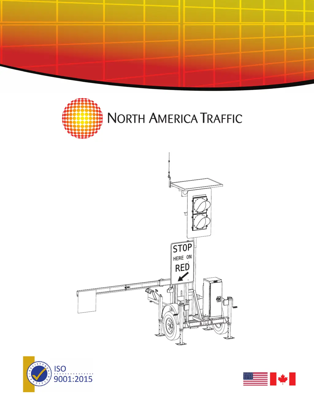
RCF 2.4
Automated Flagger Assistance
Device Manual
REV 08 02.10.22
THE LEADER IN TRAFFIC CONTROL SYSTEMS
TM

Questions and Answers

  • K
    Kelly SparksSep 10, 2025
    What does 'DEFAULT FLASH RED' mean on North America Traffic Safety Equipment?
    • N
      Natalie WoodsSep 10, 2025
      The 'DEFAULT FLASH RED' message on your North America Traffic Safety Equipment can mean that a previous fault has cleared automatically, so press the “START” button on Primary when ready to start the program. It could also mean a machine failure, in which case you should see the Primary unit for instruction.
  • M
    mgibbsAug 22, 2025
    Why does my North America Traffic Safety Equipment say 'TURN ON PRIMARY UNIT'?
    • J
      Jennifer HuberAug 23, 2025
      The 'TURN ON PRIMARY UNIT' message on your North America Traffic Safety Equipment indicates that the primary unit is either off (turn on the primary unit) or there's a communication issue. If the primary unit is on, check if the radio channel differs from the secondary unit “x” and change the radio channel on Secondary “x” to the same as Primary. Also, make sure the radio cable is attached to the radio transmitter. If the radio dip switches have been changed, set them as per diagram. A damaged antenna or radio cable can also cause this issue; replace them if necessary.
  • J
    jason08Aug 25, 2025
    Why does my North America Traffic Safety Equipment say 'TURN ON SECONDARY UNIT “X”'?
    • W
      William MillerAug 25, 2025
      The 'TURN ON SECONDARY UNIT “X”' message on your North America Traffic Safety Equipment signals that the secondary unit “x” is either off (turn it on) or experiencing communication problems. If the secondary unit “x” is on, ensure its radio channel matches the primary unit. Also, verify that the radio cable is securely attached to the radio transmitter. If the radio dip switches have been altered, reset them according to the diagram. Damaged antenna or radio cable may also be the cause; replace them if needed.
  • R
    Ronald SmithAug 27, 2025
    What to do if my North America Traffic Safety Equipment shows 'MALFUNCTION RESPONSE CHECK LAMP WIRING REPAIR MACHINE'?
    • C
      Courtney CraigAug 27, 2025
      If your North America Traffic Safety Equipment displays 'MALFUNCTION RESPONSE CHECK LAMP WIRING REPAIR MACHINE', it means that LED lamp(s) are not connected. Connect the LED lamp(s). It may also indicate a faulty controller, in which case you should replace the controller.
  • D
    Danielle FrancisAug 28, 2025
    What to do if my North America Traffic Safety Equipment shows 'MALFUNCTION RESPONSE NO LAMPS (DARK) REPAIR MACHINE'?
    • E
      Eric BryantAug 28, 2025
      If your North America Traffic Safety Equipment displays 'MALFUNCTION RESPONSE NO LAMPS (DARK) REPAIR MACHINE', it means that all LED lamps are not connected. Connect the LED lamps. It may also indicate a faulty controller, in which case you should replace the controller.
  • A
    Amanda BergerAug 29, 2025
    How to resolve 'MACHINE FAULT CHECK RS- 485 WIRING' error on North America Traffic Safety Equipment?
    • B
      becky82Aug 29, 2025
      If your North America Traffic Safety Equipment displays 'MACHINE FAULT CHECK RS- 485 WIRING', the wiring harness to the controller may be faulty, so replace the faulty harness. It can also mean that the malfunction management system link is broken, so check the unit diagnostic tab for the Malfunction management system link (checked box). Finally, it could be due to controller failure, so replace the controller.
  • W
    wattskennethSep 18, 2025
    What does 'COMMUNICATION OK PRESS START TO RESUME' mean on North America Traffic Safety Equipment?
    • W
      wilkinslindaSep 18, 2025
      The 'COMMUNICATION OK PRESS START TO RESUME' message on your North America Traffic Safety Equipment means the machine(s) are running properly. Press “Start” button on Primary when ready to start program.
  • R
    Robert LambSep 12, 2025
    What does 'DEFAULT ALL RED' mean on North America Traffic Safety Equipment?
    • K
      Kathryn TaylorSep 12, 2025
      The 'DEFAULT ALL RED' message on your North America Traffic Safety Equipment means that a previous fault has cleared automatically. Press the “START” button on Primary when ready to start program.
  • D
    Dawn RogersSep 8, 2025
    What does 'CYCLE PAUSED' mean on North America Traffic Safety Equipment and how do I resume?
    • A
      Ashley AyersSep 8, 2025
      The message 'CYCLE PAUSED' on your North America Traffic Safety Equipment indicates that the user has paused the cycle (all red) with the hand held remote. To resume, press the green button on the HHR when ready to start the program.
  • S
    Stacey KingSep 5, 2025
    What does 'PROBLEM DETECTED ON LAMP: X REPAIR MACHINE' mean on my North America Traffic Safety Equipment?
    • M
      Mary PerezSep 5, 2025
      The 'PROBLEM DETECTED ON LAMP: X REPAIR MACHINE' message on your North America Traffic Safety Equipment indicates a faulty wire connection. Check connections and reconnect wiring. It may also indicate faulty wires, so check wires and replace where necessary. The lamp itself may be faulty, so replace the faulty lamp. Finally, the controller may be faulty, so replace the faulty controller.

Summary

1 SAFETY OVERVIEW

1.1 TRAINING

Personnel operating the RCF 2.4 must be fully trained for safe operation.

1.2 TOWING

Checklist for ensuring safety while transporting the RCF 2.4 in tow.

1.3 SIGNAGE AND WORK ZONE

User's responsibility for advanced warning signs and barricades per local guidelines.

1.4 ELECTRICAL HAZARDS

Safety precautions for electrical systems, including battery disconnection.

1.5 BATTERY HAZARDS

Safety precautions for battery handling, including PPE and acid neutralization.

1.6 OVERHEAD HAZARDS

Ensure sufficient clearance for mast raising/lowering to prevent contact.

3 COMPONENT BREAKOUT

3.1 TRAILER DEPLOYED

Details about the solar panel and LED signal lamps on the deployed trailer.

3.2 TRAILER IN TRANSPORT

Components and features of the trailer when in transport configuration.

3.3 CABINET INTERNALS

Identification of internal cabinet components like controller, wiring, and charger.

4 PHYSICAL SETUP;TAKEDOWN

4.1 TRAILER SEPARATION

Step-by-step instructions for separating two nested/locked trailers.

4.2 DISCONNECT FROM TOWING VEHICLE

Detailed steps for disconnecting the trailer from the towing vehicle.

4.3 DEPLOYMENT ONSITE

Instructions for deploying the unit onsite, including sign and light post setup.

4.4 TAKEDOWN ONSITE

Steps for taking down the unit onsite, including gate arm retraction.

4.5 TRAILER CONNECTION - TWO TRAILERS NESTED;LOCKED

Instructions for connecting two trailers in a nested/locked configuration.

4.6 TRAILER CONNECTION

Steps for connecting trailers for towing purposes.

4.7 TRAILER CONFIGURATION - TANDEM TOWING

Instructions for configuring trailers for tandem towing.

5 CONTROLLER NAVIGATION

5.1 CONTROLLER HARDWARE

Identification and description of the controller's physical hardware components.

5.2 CONTROLLER SOFTWARE

Overview of the controller's software interface and displayed information.

5.3 SITE PASSCODE

Instructions for setting and managing the site passcode for system access.

5.4 INTERNAL SOFTWARE NAVIGATION

Guidance on navigating controller software menus and editing parameters.

6 MENU SCREENS

6.1 CHANGE TIMING

How to adjust signal timing parameters for different phases.

6.2 OPTIONS

Explanation of various options available in the controller menu.

Control Mode

Details on different control modes like Automatic, Manual, Pilot Car.

6.3 STARTING OPERATIONS

Steps and warnings for starting operations, including sign deployment.

6.4 HELP

Information on accessing help and viewing I/O diagnostics.

7 SETTING UP A WORK ZONE

Secondary Setup

Steps to configure secondary units in a work zone setup.

Primary Setup

Steps to configure the primary unit in a work zone setup.

7.1 LAYOUTS

Describes available work zone layouts and required units/control modes.

ONE-WAY ZONE - SINGLE UNIT

Configuration for a single unit in a one-way zone.

ONE-WAY ZONE - TWO UNITS

Configuration for two units in a one-way zone.

PILOT CAR MODE

Setup for pilot car mode operation.

TWO-WAY ZONE (MANUAL MODE)

Setup for two-way zone in manual mode.

8 RADIO REMOTE

Radio Remote Push Buttons

Description of radio remote buttons and their functions.

Radio Remote Power supply

Information about the power source and battery life of the radio remote.

Setting the Radio Channel

Steps to sync the radio remote's channel with the controller.

Generations of Radio Remote

Overview of different radio remote models and their compatibility.

9 COMPATIBILITY MODE

9.1 SETTING COMPATIBILITY MODE ON GEN 3

Steps to set up Gen 3 controllers with Gen 1 controllers.

9.2 OPERATING WITH GEN 1

Details on operating Gen 3 AFADs with Gen 1 AFAD units.

10 DATA MANAGEMENT

10.1 FAULT;DATA LOGS

How to view and export system fault and operational data logs.

10.2 SYSTEM STATUS AND DIAGNOSTICS

How to view system status, lamp status, and unit diagnostics.

10.3 SOFTWARE IMPORT;EXPORT

Steps for importing/exporting software via USB flash drive.

11 OPTIONAL EQUIPMENT

11.1 REMOTE Monitoring Services (RMS)

Overview of cellular and satellite remote monitoring services.

11.2 INTRUSION Alarm

Details about the intrusion alarm system components and application.

12 COMMUNICATIONS

12.1 RADIO SYSTEM

Best practices and common interference for radio communication.

12.2 HARDWIRE

Requirements and cable specifications for hardwired connections.

13 POWER SYSTEM INFORMATION

13.1 SOLAR

Information about the solar panel, its regulation, and maintenance.

13.2 BATTERIES

Details on battery types, autonomy, and factors affecting performance.

13.3 CHARGER

Information about the battery charger, its specifications, and connection.

13.4 GENERATOR USE

Requirements and precautions for using a generator.

14 GENERAL MAINTENANCE

14.1 TRAILER MAINTENANCE SCHEDULE

Monthly maintenance schedule for trailer components.

15 TROUBLESHOOTING

TURN ON SECONDARY UNIT X

Primary unit waiting for secondary unit communication.

TURN ON PRIMARY UNIT

Secondary unit waiting for primary unit communication.

REPAIR COMMUNICATION RADIO MODEM

Controller not recognizing radio modem connection.

REPAIR COMMUNICATION

Communication failure seen by the primary unit.

SITE INTERFERENCE CHANGE RADIO CHANNEL

Units recognizing radio interference.

PROBLEM DETECTED ON LAMP: X REPAIR MACHINE

Overload or underload on lamp outputs.

ATTENTION: SEE PRIMARY UNIT

Secondary unit sees a problem with the primary unit.

ALL STOP

System in an all red state due to remote or controller.

BATTERY LOW CHARGE FOR 48 HRS

Battery bank voltage is reading low.

MALFUNCTION RESPONSE NO LAMPS (DARK) REPAIR MACHINE

Malfunction detected: no lamps displayed.

MACHINE FAULT CHECK RS-485 WIRING

Communications timeout on the RS-485 network.

HOLD FOR RAILROAD

Cycle paused for railroad preemption.

North America Traffic RCF 2.4 Specifications

General IconGeneral
BrandNorth America Traffic
ModelRCF 2.4
CategorySafety Equipment
LanguageEnglish

Related product manuals