EasyManua.ls Logo

North Atlantic SRS 5330A User Manual

North Atlantic SRS 5330A
24 pages
To Next Page IconTo Next Page
Page #1 background imageLoading...
Page #1 background image
5330A Operations Manual
SYNCHRO/RESOLVER SIMULATOR
TWO SYNCHRO/RESOLVER OUTPUTS (UP TO 6 VA)
PLUS OPTIONAL 6 VA REFERENCE SUPPLY
North Atlantic Industries, Inc.
631.567.1100 / 631.567.1823 (fax)
6/12/2018
5330A Operations Manual Rev A6
110 Wilbur Place, Bohemia, NY 11716
www.naii.com
Cage Code: 0VGU1
Page 1 of 24
GENERAL
This Operations Manual contains a general description, specifications, installation & operating instructions, as well
as maintenance and calibration verification information for the North Atlantic Industries (NAI) Model 5330A
Synchro/Resolver Simulator.
The 5330A is a replacement for all standard variations of the legacy 5310 & 5330 (see P/N).
For special versions (P/N = 5310 Sxxxx or 5330 - Sxxxx), contact factory to determine compatibility.
DESCRIPTION
This second generation Simulator, Model 5330A, represents a major step forward by using digital technology to
produce Synchro and Resolver outputs. The use of an intelligent DSP design eliminates push buttons and allows
all programming to be done either via an integrated touch-screen, jog-wheel, or a mouse interface. In addition,
IEEE-488, USB, and Ethernet interfaces have been added to extend remote operation capabilities.
The angle outputs can be set for one of two display modes: 0-360º or ±180°. A wide (47Hz to 10KHz) frequency
range is standard. The versatility of this device has been substantially increased by incorporating dynamic modes
that enable user to test servo systems under various simulated stringent field conditions.
a. Each channel can be set to simulate a rotating component in either clockwise or counter-clockwise
direction.
b. Each channel can be set to produce either Step, Sine wave, Ramp, or Saw tooth outputs.
Improved flexibility is provided by two fully independent outputs that can be combined to operate as a two-speed
output. The gear ratio, for the two-speed mode, is programmable from 2:1 to 255:1. When used in conjunction
with North Atlantic Industries Model 8810A Angle Position Indicator, the Instrument pair can perform the classic
Dummy Gun Director functions.
The 5330A can generate output voltages from 1.0 to 90 V
L-L
and accept reference voltages from 2 to 115 V
RMS,
over a frequency range of 47Hz to 10KHz and can, therefore, handle most known Synchro/Resolver simulation
requirements.
Optional Reference: This design can also incorporate a 6 VA programmable reference generator that is used for
standalone applications (See P/N).
FEATURES
Up to two channels
Optional reference supply
47 Hz to 10 KHz
Up to 6 VA power output per channel
Output protection
Dynamic Modes
Ethernet, IEEE-488, USB & Parallel ports
Replaces NAI 5310/5330

Table of Contents

Question and Answer IconNeed help?

Do you have a question about the North Atlantic SRS 5330A and is the answer not in the manual?

North Atlantic SRS 5330A Specifications

General IconGeneral
BrandNorth Atlantic
ModelSRS 5330A
CategoryLaboratory Equipment
LanguageEnglish

Summary

GENERAL INFORMATION

PRODUCT DESCRIPTION

Overview of the Synchro/Resolver Simulator and its technological advancements.

KEY FEATURES

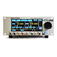
Highlights of the 5330A's capabilities, including channel count, output power, and connectivity.

SPECIFICATIONS

SYNCHRO/RESOLVER SPECIFICATIONS

Detailed technical parameters for Synchro and Resolver output modes.

REFERENCE GENERATOR SPECIFICATIONS

Performance data for the optional reference generator module.

GENERAL OPERATIONAL SPECIFICATIONS

Information on interfaces, environment, power, and physical characteristics.

SAFETY SUMMARY

GENERAL SAFETY AND REPAIR NOTES

General precautions, repair restrictions, and safety measures during operation and maintenance.

CRITICAL ELECTRICAL SAFETY WARNINGS

Warnings regarding high voltage, shock hazards, and continuous input power safety.

INTERFACES AND COMMUNICATION

J1 CONNECTOR PIN DESIGNATIONS

Pinout details for the 78-pin and DE9PP J1 connectors.

J2 CONNECTOR IEEE-488

Pin designation details for the IEEE-488 standard interface connector.

J3/J4 USB & ETHERNET CONNECTORS

Description of USB and Ethernet connectors for communication and mouse input.

CONTROLS AND INDICATORS

FRONT PANEL OVERVIEW

Description of front panel controls, buttons, knobs, and display indicators for user interaction.

CHANNEL SELECTION AND MODES

CHANNEL SELECTION PROCEDURE

Steps to select Channel 1, Channel 2, or Dual Channel configurations.

SYNCHRO/RESOLVER MODE SELECTION

Procedure to toggle between Synchro and Resolver output formats.

OUTPUT VOLTAGE AND PHASE CONTROL

VOLTAGE LINE-TO-LINE (VLL) SETTINGS

Setting the desired output voltage (VLL) and choosing FIXED or RATIOMETRIC modes.

ANGLE AND PHASE OFFSET ADJUSTMENT

Configuring output angle and phase shift for simulation accuracy.

REFERENCE SOURCE MANAGEMENT

OUTPUT AMPLIFIER ENABLE/DISABLE

Turning the output amplifiers ON or OFF using the Output button.

INTERNAL AND EXTERNAL REFERENCE SELECTION

Selecting and setting up either the internal or external reference voltage source.

REMOTE SENSE AND OVER CURRENT PROTECTION

REMOTE SENSE SETUP CONFIGURATION

Configuration for remote sensing of SIM channels and reference supply.

OVER CURRENT DETECTION AND RESET

Details on overload detection, output stopping, and resetting the over current condition.

ADVANCED PARAMETER SETTINGS

DELTA SCREEN PANEL FOR KNOB RESOLUTION

Setting parameters for the increment/setup knob resolution for functions like Angle Set.

MULTI-SPEED (RATIO) MODE OPERATION

Combining two outputs for two-speed operation with programmable gear ratios.

DYNAMIC MODES AND PROGRAMMING

DYNAMIC MODE SELECTION AND CONTROL

Selecting and programming dynamic output modes like Rotation, Step, Sine, Ramp, or Saw tooth.

PROGRAMMING AND LEGACY SYSTEM COMPATIBILITY

Remote control via USB/Ethernet/IEEE-488 and compatibility with legacy 5330/5310 systems.

REMOTE OPERATION PORT CONFIGURATION

USB PORT CONFIGURATION FOR REMOTE CONTROL

Configuring the unit to operate via the USB port for remote control.

ETHERNET PORT CONFIGURATION FOR REMOTE CONTROL

Configuring the unit to operate via the Ethernet port for remote control.

IEEE-488 PORT CONFIGURATION FOR REMOTE CONTROL

Configuring the unit to operate via the IEEE-488 port for remote control.

SETUP MENUS AND OPTIONS

NAVIGATING THE SETUP MENU

Accessing the setup menu to configure various simulator parameters.

OPTIONS MENU CONFIGURATION DETAILS

Setting display formats, input modes, touchscreen, and auto-save features.

SETTING PRESETS AND DISPLAY ADJUSTMENT

FACTORY SETTINGS MANAGEMENT

Loading and using pre-configured parameter sets stored at the factory.

CUSTOM SETTINGS SAVING AND LOADING

Saving and loading up to nine user-defined parameter configurations.

FRONT PANEL BRIGHTNESS CONTROL

Adjusting the front panel backlight brightness level.

CALIBRATION AND SYSTEM HELP

CALIBRATION MENU FUNCTIONS

Accessing routines for touchscreen and instrument self-calibration.

HELP MENU AND SYSTEM INFORMATION

Displaying specification summaries, button descriptions, and unit system information.

DEFAULT VALUES RESTORATION

Restoring the 5330A to its original factory settings.

ORDERING INFORMATION AND ACCESSORIES

PRODUCT ORDERING GUIDELINES

Details on part numbers, options, and how to order the 5330A and its variants.

INCLUDED ACCESSORY KITS

List of accessory kits and their components included with the 5330A.

OPTIONAL RACK MOUNTING ACCESSORY

Information on the optional rack mounting adapter for the 5330A.

INSTALLATION AND MAINTENANCE PROCEDURES

UNPACKING AND INITIAL INSPECTION

Procedures for inspecting the instrument upon arrival for any shipping damage.

INSTALLATION GUIDELINES (RACK AND BENCH)

Instructions for both rack mounting and bench top installation of the unit.

MAINTENANCE TASKS (FUSES, FAN FILTER)

Guidelines for maintaining the instrument, including fuse replacement and cooling fan filter.

SERVICE AND CALIBRATION PROCEDURES

REPAIR POLICY AND HIGH VOLTAGE SAFETY

Instructions regarding factory-only repairs and critical safety precautions for high voltage.

REAR PANEL COOLING FAN FILTER MAINTENANCE

Maintenance guidance for cleaning or replacing the cooling fan filter.

SELF-CALIBRATION AND VERIFICATION PROCESS

Details on the unit's automatic self-calibration and the process for annual calibration verification.

MECHANICAL OUTLINE AND CONNECTOR DETAILS

MECHANICAL OUTLINE AND DIMENSIONS

Diagrams showing the physical dimensions and layout of the SRS 5330A.

J3 AND J4 CONNECTOR SPECIFICS

Specifics on the USB and Ethernet (J3) and USB (J4) connectors on the rear and front panels.

EUROPEAN UNION SUPPLEMENTAL INFORMATION

EU UNION GENERAL AND SPECIFICATIONS

General information and specific specifications applicable to units sold in the European Union.

EU UNION SAFETY, INSTALLATION, AND USAGE

Guidance on line cords, mains input, safety grounding, and proper usage for EU units.

EU UNION TECHNICAL ASSISTANCE CONTACT

Contact information for technical support for units sold within the European Union.

DECLARATION OF CONFORMITY

CERTIFICATE OF CONFORMANCE DETAILS

Details of the Certificate of Conformance, including testing standards and equipment identification.

REVISION HISTORY

MANUAL REVISION LOG

A log of changes made to the manual across different revision levels.