General
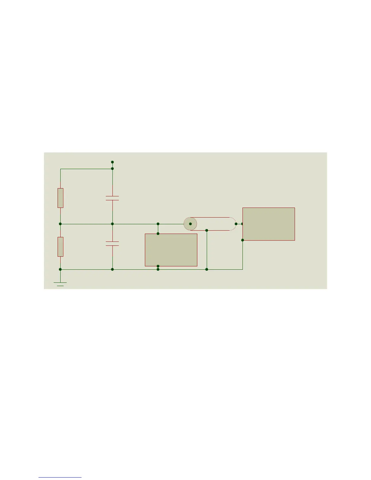
The PVM and VD series high voltage probes are RC dividers designed to produce
precisely attenuated signals over a very wide bandwidth. The circuit diagram is shown
below. The divider network consists of a high voltage network represented by a parallel
capacitor and resistor, and a low voltage network which consists of a parallel RC
network and a compensation circuit. The high voltage section of the voltage divider is in
a polypropylene oil filled housing. The low voltage section is in the small rectangular
box or circuit board inside the bottom of the handle (PVM series probes) or in the small
rectangular box underneath the probe base (VD series probes). The purpose served
by placing the low voltage section in a secondary enclosure is that it reduces noise.
Additional compensation for high frequencies is used in the PVM-2 and PVM-6.
Generalized Probe Configuration
The probe is designed to produce the calibrated level of output with a 1 Megohm
impedance on the measurement device, and with the specified cable length in place.
Changes in cable length tend to change the calibration approximately 0.5 %/ft. for a
typical 1000:1 probe. The 10,000:1 probes, including the VD series probes, have
smaller variations in calibration with cable length.
The high voltage section of each probe is insulated with Shell Diala-AX or Ergon Hivolt
transformer oil which does not contain PCBs. The oil does not have any known toxic
effects. It is the same transformer oil used throughout the world in distribution
transformers.
RHV
CHV
RLOW
CLOW
Scope or Meter
Connection Coax
Additional
Compensation
HV Input
 Loading...