Pulse Output Module
Page - 2 -
1 Pulse Output Module
1.1 Description
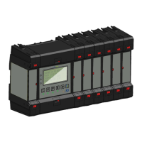
The multicube pulse output module is a 12 channel relay board with one side of each relay
connected to a common terminal. The module connects as one or more of up to ten
option modules to the right hand side of the multicube main display. Each of the 12
channels can be configured to act as either a pulse output responding to changes in
accumulating energy registers or as an alarm output responding to level changes of
instantaneous registers.
The pulse output module has a Modbus ID determined by the ID of the main display unit and
the position the unit is placed in the option modules. One pulse module replaces one meter
module or two metering units. The Modbus tables described later are accessed on this ID.
Multiple pulse modules can be connected to the multicube with corresponding reduction of
the maximum number of meter modules.
2 Safety
This manual gives details of safe installation of pulse output modules for connection to the
multicube electricity metering systems. Safety may be impaired if the instructions are not
followed or the system is used in a manner not specified by the manufacturer. Labels give
details of equipment ratings for safe operation. Take time to examine all labels before
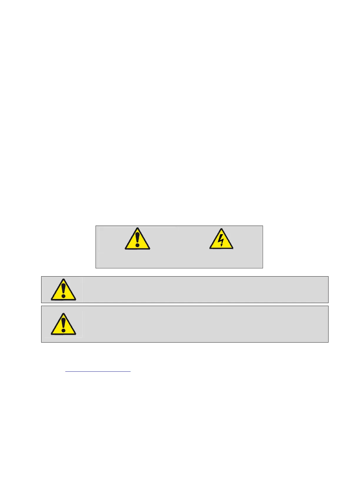
commencing installation. Safety symbols on the meter have specific meanings.
Caution Risk of Danger
Refer to Instructions
Danger
Risk of Electric Shock
Safety may be impaired if the instructions are not followed or the module or
metering system is used in a manner not specified by the manufacturer.
Contains no user serviceable parts. Field wiring and commissioning should only be
carried out by qualified personnel, in compliance with applicable national
regulations.
e.g. National Electrical Code (NEC) for US; Canadian Electrical Code for Canada
For further Information contact the manufacturer:
Address: Northern Design (Electronics) Ltd: 228 Bolton Road, Bradford, West Yorkshire, BD3 0QW. (UK)
Web: http://www.ndmeter.co.uk
2.1 Maintenance
The equipment should be maintained in good working order. Damaged equipment must be
returned to the manufacturer (or his authorized agent) for repair. The meter may be cleaned
by wiping lightly with a soft cloth. No solvents or cleaning agents should be used. All inputs
and supplies must be isolated before cleaning any part of the equipment.