Do you have a question about the Northern N-1000-IV and is the answer not in the manual?
Introduces computerized control over entry and its benefits over traditional keys.
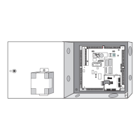
Details the N-1000-III/IV control panels as decision-making units in the access control system.
Describes using PCs, printers, or data terminals for programming N-1000-III/IV control panels.
Details the interface between programming devices and control panels via 20 mA current loop.
Explains the interface for 485 multi-drop communications bus.
Discusses the role of PROM chips in determining panel features and commands.
Specifies the required AC or DC power supply for the N-1000-III/IV panel.
Details the 12 VDC and 5 VDC output power capabilities for connected devices.
Describes the 12 VDC battery backup capabilities and its operational duration.
Explains the configuration options for alarm input points (NO/NC, supervised/unsupervised).
Details the DPDT relay contacts and their ratings for inductive and dry circuit loads.
Details the Four Reader Board for N-1000-IV, its connections, and function.
Describes the relay contact terminations for terminal blocks 1, 2, 3, and 4.
Details Terminal Block 5 for Wiegand card readers and alarm point common (N-1000-III only).
Details Terminal Block 6 for alarm input points 5-16.
Describes terminals for 485 communication, alarm inputs 1-4, and 20 mA loop.
Details Terminal Block 8 for 11-conductor keypad connections and alarm point common.
Details Terminal Block 9 for power supply and auxiliary connections.
Explains DIP switch settings for baud rate and control panel address.
Details the function of various jumpers for configuring panel operation modes.
Describes connectors for AEP-3 expansion boards and battery wires.
Lists the functions, colors, and indications of the N-1000-III/IV LEDs.
Explains the use of the restart button for panel reset and DIP switch activation.
Discusses RAM chips for database and transaction buffer memory.
Describes PROM chips storing program and control logic memory.
Provides recommended installation techniques and practices for N-1000 panels.
Explains how card readers and keypads transmit data, use time zones, and activate outputs.
Describes alarm input point states (physical/software) and configuration options.
Details relay output states (DE-ENERGIZED/ENERGIZED) and wiring requirements for locks.
Explains default interlocks, pulse times, and shunt times for system configurations.
Describes the auto-relock feature for immediate re-locking and re-arming of doors.
Explains how to use Time Zones to control door access for free access periods.
Details wiring for Wiegand output card readers, including LED control and ground connections.
Explains wiring connections for the Four Reader Board on the N-1000-IV panel.
Details wiring for 11-conductor keypads using a 2 of 7 matrix configuration.
Recommends cable types and grounding for alarm input points.
Recommends cable types for relay output points and their distance limitations.
Covers wiring requirements for various communication methods like 20 mA and RS-485.
Details cable requirements for connecting a PC to the C-100-A1 Converter.
Explains wiring for the 20 mA communication loop from C-100-A1 to panels.
Describes connecting AEP-3 Relay Expansion Boards to the N-1000-III/IV panel.
Details connecting a PC to the N-485-PCI-2 for RS-485 communications.
Explains wiring for 485 multi-drop communications using N-485-PCI-2.
Explains the requirement for bias and EOL resistors for clear 485 transmissions.
Lists NCI part numbers, AWG, description, and max distance for various cables.
Provides pinout configurations for RS-232 ports with various devices.
Illustrates the proper installation of the S-4 Suppressor Kit across relay contacts and near electrical loads.
Shows the panel grounding point and preferred chassis earth ground connection.
Illustrates connections for AC, optional external DC, and 12 VDC backup battery power.
Explains the conventions used for commands, variables, and syntax in the guide.
Lists common error messages and their corresponding violations in code entry.
Provides a chronological guideline for programming commands.
Lists the available programming commands in alphabetical order for quick reference.
Assigns reading devices to activate specified input, output points, and groups.
Establishes time zones for PIN usage and pulses points based on invalid code uses.
Sets the method for interpreting card read data for Wiegand type cards.
Defines output point groups and special output groups.
Sets holiday dates and allows deleting existing holiday entries.
Initializes control panels, enables features, and sets site codes.
Sets control panel buffer/print options and anti-passback mode.
Provides manual control and sets special options for input/output points and groups.
Sets interlocks between alarm input points and/or output points.
Generates control panel database reports for system monitor and printer.
Sets the control panel time.
Assigns shunt times and time zones to input/output points with special options.
Programs input points for NO/NC and Supervised or Non-Supervised operation.
Creates groups of inputs (Zones) and allows shunting of multiple inputs.
Allows a card to activate different groups when used at different readers.
Lists improvements like four-layer PWB, switching regulators, and improved canister.
Discusses the memory chips used in the panel and their capacity.
Lists the functions and indications of the N-1000-III/IV LEDs, including rearranged and new ones.
Troubleshooting steps for resolving N-1000-III/IV panel lock-ups.
Steps to troubleshoot communication issues with 20 mA systems.
Details the built-in test capability for checking circuit board hardware functionality.
| Brand | Northern |
|---|---|
| Model | N-1000-IV |
| Category | Control Panel |
| Language | English |