Installation
START / impulse input
(OPEN / STOP / CLOSE)
Safety photocell, two or four-wire
Emergency-STOP, slack cable, latching
Limit switch rest position
Aerial
Protective conductor contact
Hydraulic valve
Floating relay output
Floating relay output
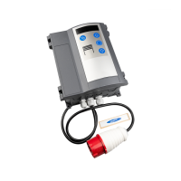
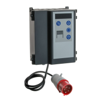
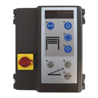
The control unit comes ready-wired with a 16A CEE
phase-changer plug andapprox. 1 m of cable (see ).
Wrong connection of mains voltage
A mains isolator is provided for
disconnection of all poles of the mains
voltage. Secure the mains isolator against
unauthorised use during maintenance
or repair.
A sensor and limit switch for the automatic return
function can be installed besides the valve
connection.
Remove the jumper and connect the emergency stop
button. Pressing the emergency stop button stops
the dock leveller, no free floating position.
Required for combined operation with mutual
interlocking (menu 17=0). The door can only be
closed at zero position.
br - brown
gr - grey
bk - black
Possible connection of a wheel chock sensor.
Selection of menu 15 = 1.
The dock leveller can only lift and extend when the
wheel chock is applied.
br - brown
gr - grey
bk - black
When using a key switch / pull button, the desired
function in menu 50 should be selected.
Requiredtools
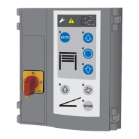
Installingthecontrolunit
Openingthecontrolunitcover
4a
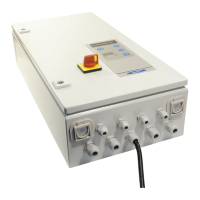
Mainsisolator
Connectionofhydraulicmotor
Valveconnection
Emergencystopbutton
Sensorzeroposition
Wheelchock
Keyswitch/pullbuttonconnection
Connections
Designation:
Mainsconnection
J1
J2
J3 Closing edge OSE / 8K2 / DW
J4
J5
J6 Wheel chock
J7 Key switch / pull button
J9 Digital limit switch - motor cabel
J10 Connection add-on controls
J11 Connection radio receiver
J12
J13 Membrane key pad
J14 Communication interface
X1 Mains connection
X2 Mains output L, N (500W / 230V)
X3
X4
X5 1, door status relay
X6 2, door status relay
X7 Door operator
X8 Hydraulic valves, sensors
can
destroy the control.
Observe rotating field.
!
0
1
2
3
4
5
6
7
8
9
Relay output
Motorconnection
Motorconnectinglead
Impulsegeneratorconnection
13b
13d
Photocellconnection
14a
14b
14c
Safetyedgeconnection
15a
15b
15d
Radioremotecontrol
2 change-over contacts:
max. 250VAC / 2A or 24VDC / 1A.
24V-output X8: max. 100mA
Selecting the relay function in menu 45 and 46.
Connect the motor to agree with the available mains
voltage.Also see fig. 4.
The connecting lead for the motor and digital limit
switch (DES) is pre-assembled and ready to use -
attach accordingly.
If the gate is to be opened and closed by way of a key
(Open-Stop-Closed), select the following:
Set value 1 in menu 51 or
Menu 50, factory setting
The photocell must be correspondingly set/adjusted
in menu 36.
Two-wire photocell LS2
During this process the closing
procedure must not be interfered with,
otherwise the wrong position could be
recorded.
Four-wire photocell LS5 with self-testing
Reflection photocell RLK29
If in the menu the frame-fitted photocell has been
selected, the next time the door closes the control
unit automatically initiates a learning run to detect the
position.
When using impulse control for door closing,
connection of a safety edge is required. Select the
corresponding setting in menu 35.
Optical closing edge OSE
Electrical safety edge 8K2 with a termination
resistor of 8.2 kOhm
Pressure wave edge and switch with a loop
resistance of 8.2 kOhm
Plug in receiver module (option) at J11 and initiate
the hand transmitter learning procedure in menu 60
or 62.
Electrical safety edge 8K2 in series connection
with slack rope and wicket door switch
15c
10
11
12
13
14
15
16
Programmingthecontrolunit
!
Programming is menu-driven. Make all settings as
shown in the schematic.
Protected settings are identified by the letter in the
display and access to the menu is barred. To release
the menu, the release signal must be sent with the
infrared control.
If the set overcurrent is exceeded, the control will
switch off the pump.
Lift the dock leveller until the pressure relief valve
trips. Now keep button in menu 10 pressed for 5
sec; the value achieved for the motor current will now
be displayed. Make sure that the set value is larger
than the one displayed.
When the return button is pressed, the dock leveller is
lifted for the time set and then lowered safely to zero
position.
The control for initial start-up in menu 17 = 4 is set to
dock leveller operation mode. The respective
function should be set as soon as the door is started
up.
Make sure that the door and the dock
leveller cannot crash.
Compensates changes in the closed position
resulting from temperature fluctuations, gearbox run-
in etc.
Compensates changes in the closed position
resulting from cable elongation or a rise in the floor
level. Set the precise closed position beforehand,
then set in menu 43.
The positions taught in menus 31, 34 and 37 are
adapted accordingly in settings 2, 3 and 4.
If the set value is exceeded, error E32 is displayed.
After the springs have been renewed,
the door end-of-travel positions need to be reset.
Motor 9.24/5.24: input value = U x weight / 20 kg
Motor 9.20: input value = U x weight / 16 kg
Motor 9.15: input value = U x weight / 15 kg
Motor 9.24, U = 8 revolutions to open the door
Weight of the door leaf = 150 kg, each of the 2
springs bears 75 kg. Cut-off recommended at 60 kg.
= 8 x 60 kg / 20 kg =
The quick release requires re-setting,
otherwise spring fracture safeguards
must be connected.
Press the button of menu 47 for 5 sec rather than
only briefly, after the door has been completely
opened and closed once.
The value indicates how the door is balanced:
Motor 9.24/5.24: F (kg) = display value x 20 kg / U
Motor 9.20: F (kg) = display value x 16 kg / U
Motor 9.15: F (kg) = display value x 15 kg / U
U = number of revolutions for one door opening
If the display value ranges between -2 and -9, the
springs are over-tensioned.
The results are only approximate values; a force
measuring run is required to determine the value
more precisely.
L
Hydraulic motor overcurrent (menu 10)
Display of the actual value
Automatic time (menu 13)
Dock leveller – door operation options (menu 17)
Correctingtheslowing-downpath(menu42)
Level adjustment (menu 43)
Spring breakage detection (menu 47)
Example:
Inputvalue 24
Checkofthespringbalancingdevice
!
When using 6.65DU, the function will be
different. Please refer to section “DU
Functions” for more details.!
GB
 Loading...