Do you have a question about the Novus N1040 and is the answer not in the manual?
Highlights important operational and safety information, including cautions and electrical shock hazards.
Provides guidance on minimizing electrical noise, using shielded cables, and ensuring a clean mains supply.
Step-by-step instructions for mounting the controller onto a panel using mounting clamps.
Illustrates the terminal connections for power, inputs, and outputs on the back panel of the controller.
Details sensor types accepted and their respective codes/ranges, configurable via the EYPE parameter.
Describes the available output channels (Control, Alarm 1/2, LBD) and their functionalities.
Explains control strategies like ON/OFF and PID, including the auto-tuning function.
Details the 2 assignable alarm channels and their various trigger functions (Lo, HI, Differential, Sensor Break).
Option to inhibit alarms during initial energization or transition from run, except for sensor break.
Defines a user-assigned output value for the control output in case of sensor failure (Err alarm).
Detects control loop breaks by monitoring PV reaction time to control output signals.
Allows fine adjustments to the PV reading to compensate for sensor errors.
Explains using the USB interface with NConfig software for configuration, monitoring, and firmware updates.
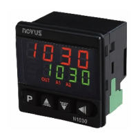
Identifies and describes the function of the controller's front panel components: Display, Indicators, and Keys.
Details the controller's behavior upon power-up, including firmware version display and initial operation.
Defines parameters related to the operation cycle, including PV, SP, and alarm setpoints (SPA1, SPA2).
Covers PID tuning parameters like Auto-Tune (Atun), Proportional Band (Pb), Integral Rate (Ir), and Derivative Time (dt).
Allows assigning functions (Control, Alarm, LBD) to the controller's output channels OUT1 through OUT4.
Configures alarm functions, activation points, blocking, and visual signaling options.
Sets up input type, digital filter, decimal point, unit display, offset, limits, and communication settings.
Includes password entry, calibration enable, low/high input calibration, and factory restore options.
Details access passwords, protection levels, password change, protection access lockout, and master password.
Steps for executing PID auto-tuning (FASE or FULL) and waiting for the TUNE indicator.
Provides guidance for manual adjustment of PID parameters (Proportional, Integral, Derivative) based on process behavior.
Lists common controller problems like connection errors and programming issues, with corresponding messages.
Procedure for calibrating the input signal, including applying signals and adjusting parameters.
Details RS-485 compatibility, MODBUS RTU protocol, connection specifics, and signal lines.
Configures parameters for serial communication, specifically communication speed (bRud) and address (Addr).
Describes the MODBUS RTU slave protocol, available commands, and holding registers for serial communication.
Explains identification codes for output features, digital communication, and power supply options.
Lists detailed specifications including dimensions, power supply, environmental conditions, input/output details, and certifications.
Advises contacting local distributors for service as the product contains no serviceable internal parts.
Outlines the one-year warranty for defects in material and workmanship and limitations of liability.
| Number of Inputs | 1 |
|---|---|
| Control Algorithm | PID, ON/OFF |
| Communication | RS485 Modbus RTU |
| Operating Temperature | 0 to 50°C |
| Input Type | Thermocouple, Pt100, 4-20mA, 0-50mV |
| Control Output | Relay, 4-20 mA |
| Display | Dual 4-digit LED |
| Power Supply | 100-240VAC |
| Alarm | 2 configurable alarms |
| Protection | IP65 front panel |
| Number of Outputs | Up to 4 |