11 12
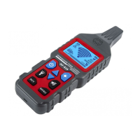
3.1.2 Locating and tracing of lines and sockets
Preconditions:
The circuit must be dead.
※ Neutral line and protective ground wire must be connected and fully operational.
※ Connect transmitter to phase line and protective ground wire according to Fig.3-1-2.
※
Fig 3-1-2
1. Full grounding should be ensured.
2. With the one-pole indication, also lateral circuit branches can be traced (The fuse
must be removed in this example).
3. lf the supply cable fed with the signals via the transmitter is located, e.g. directly
in parallel to other conductors (e.g. cable groove or duct), or if these conductors
are crossed, the signals are also input into the other conductors.
4. During locating and tracing, the stronger the signal displayed, the closer the
locator is to the lines to be traced.
5. Adjust the transmitting power level of the transmitter to adapt it to different
detection radiuses.
6. The target position can be precisely located by your setting of the manual mode
of the receiver and selecting of proper sensitivity.
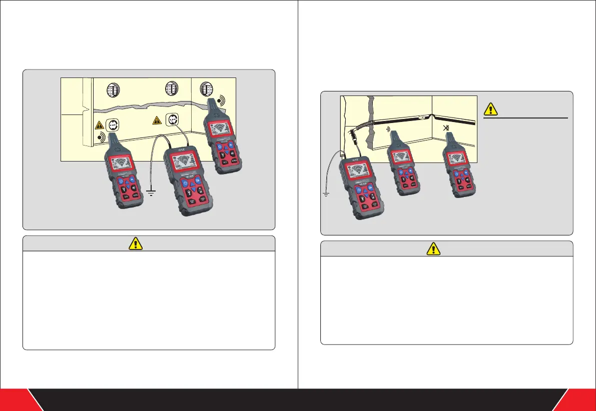
3.1.3 Detect the narrow (blocked) part of the laid non-metallic
pipeline
Preconditions:
The pipeline must be made of non-condactive materials (such as plastic);
※ The pipeline must not be charged;
※ The transmitter is connected to a metal helical tube (metal tube or flexible conduit)
and an auxiliary ground wire, as shown in Fig.3-1-3;
※ The measuring method is the same as that used in the example.
※
1.If there is current in the
pipeline, cut off the power,
and correctly earth it when
the pipeline is not charged.
2.The grounding end should
be properly grounded, and
the grounding end of the
transmitter should be a
certain distance away from
the pipeline to be measured.
If the said distance is too
short, the signal and the
circuit cannot be precisely
located.
Fig 3-1-3
1.If you only have one helical tube that is made of non-conductive material (such
as made of fiberglass), we suggest that you insert a metal wire with the section
area of about 1.5mm² into the non-conductive helical tube, and then push it into
the narrow part.
2.ln the process of detecting the pipeline, the stronger the signals displayed on the
Nixie tube of the detector, the closer the pipeline detected by the detector.
3.ln the process of detecting along the pipeline, ifthe signals received by the
receiver is suddenly attenuated, the detected position is where the blockage
locates.
4.Adjust the transmitting power of the transmitter to adapt to different radiuses of
detection.
Your excellent helper in measuring instruments. Your excellent helper in measuring instruments.
HINTS
HINTS
CAUTIONS