4
5.Adjustment method (Refer to P. 23 and after of operation manual)
<Kind of feedback modes at time of driving>
Feedback control operations at time of driving of K-ECG25 are following three kinds:
(A) Constant voltage mode:
This is a mode generally used (Initial setting at the time of shipment). It
controls the constant voltage so that the load (output) voltage becomes the
value set by the speed adjustment knob.
(B) Constant amplitude mode: Select this mode when the weight variation of work is large or more
stable feeding operation is required.
(C) Resonance point tracking mode: To drive more efficiently, this controls so that the amplitude
becomes steady at the resonance point of parts feeder. In the resonance
point tracking mode, the constant amplitude control also becomes ON at
the same time.
Note) Before adjusting each mode, please confirm that all wirings ended and there is no work in the bowl or
on the chute, and then set functions of J01 and J04. Moreover, before adjusting the constant amplitude
mode and resonance point tracking mode, please install vibration sensor and set function J06 and J07
with the resonance point tracking mode.
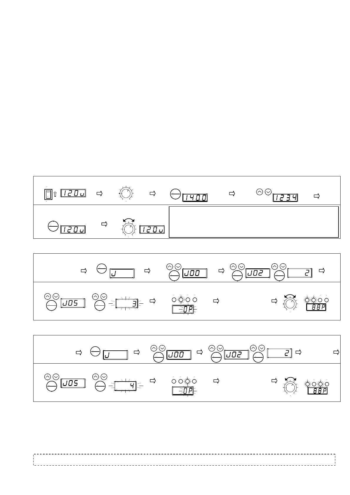
(A)Adjustment method of constant voltage mode (Refer to P. 26 of operation manual)
(B)Adjustment method of constant amplitude mode (Refer to P. 28 of operation manual)
(C)Adjustment method of resonance point tracking mode (Refer to P. 31 of operation manual)
Refer to operation manual for details of driving and adjustment.
6.Trouble shooting
In the event that any trouble occurs, please refer to P. 54 to 56 of operation manual.
Revised July 1, 2013 4th edition
NTN Technical Service Corporation
Contact: East Japan district (Tokyo) 03-6713-3652 Central Japan district (Nagoya) 052-222-3291 West Japan district (Osaka) 06-6449-6716
OFF
ON
O
I
SPEED
①Power ON (in operation)
②Knob scale: about 5
③Data one push (Frequency displayed )
④Frequency adjustment (set slightly higher than resonance
point)
※Points for frequency adjustment
Max. amplitude point (resonance point) of the part feeder is searched lowering the
frequency from the initial value (ECG25:140Hz,ECJ45:70Hz)gradually with the down key.
After that, drive by
frequency (3~10Hz) slightly higher than resonance point. Then vibration
becomes stead
.
SPEED
⑥ Adjust amplitude with knob
⑤ Data push twice (Voltage display)
DATA
ENTER
DATA
ENTER
SPEED
RUN Vib.
Fre.A LIMIT
RUN Vib.A Fre.A LIMIT
⑦ Return J02 to the
original state or push
the RUN key to driving
state.
②Function long push
③Select function J
④ Select J02 and then select 2 (Stopping state)
①Implement ①~④ of constan
voltage mode
⑤Select J05 then select 3 (Calibration begins)
⑥Calibration ends
⑧Adjust amplitude with knob
Gain is automatically adjusted
FUNC
RESET
DATA
ENTER
DATA
ENTER
DATA
ENTER
DATA
ENTER
DATA
ENTER
RUN Vib.A Fre.
LIMIT
①Implement の of
constant voltage
mode
⑥Select J05 then select 4 (Calibration begins)
SPEED
RUN Vib.A Fre.A LIMIT
fter automatic search of resonance frequency,
gain is automatically adjusted.
②Function long push
⑤Set J04, J06 and
J07
③Select function J
④Select J02 then select 2 (Stopping state)
⑦Calibration ends
⑧ Return J02 to the
original state or push
the RUN key to driving
state.
⑨Adjust amplitude with knob
FUNC
RESET
DATA
ENTER
DATA
ENTER
DATA
ENTER
DATA
ENTER
DATA
ENTER
 Loading...