GRILLE INSTALLATION
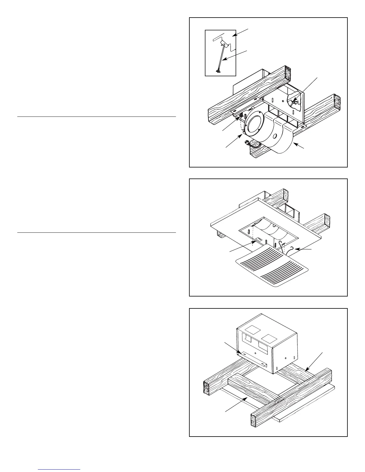
1. Refer to Figure 8. Squeeze grille mounting springs and insert
into slots in the housing.
2. Press grille firmly into place against ceiling.
MAINTENANCE
•
WARNING: Risk of fire or electrical shock; disconnect the power
before cleaning or performing any maintenance on the ventilator.
•
If the grille becomes soiled, use only a mild soap and water
solution for cleaning. Do not use solvents or abrasive cleaners.
INSTALLATION
IN EXISTING CONSTRUCTION
Installing a ventilator in an existing construction site requires at
least a small accessible area (attic or crawl space) above the
planned installation location.
Review “INSTALLATION IN A NEW CONSTRUCTION SITE” and
follow all instructions which apply to your installation.
Locate the ventilator next to a ceiling joist.
Plan the ductwork and wiring before proceeding with the installation.
CAUTION: Check the area above the planned installation to
ensure that:
1. Ductwork can be installed or that the area is sufficient for proper
mounting.
2. Wiring can be run to the planned location.
3. No wiring or other obstruction will interfere with the installation.
INSTALLATION FROM ACCESSIBLE
AREA ABOVE (USING HEADERS)
1. From below the installation site, drill a small hole in ceiling at the
planned location.
2. Locate hole in attic or crawl space.
3. In attic or crawl space, mark ceiling for cutout by using the housing
as a template. Cutout dimensions: 10
3
⁄16" x 14
1
⁄
2
". The short side
(10
3
⁄16") of the cutout must be right next to the ceiling joist.
4. Refer to Figure 9. Mark cutout along marked line.
NOTE: If ceiling is plaster, cutout should be made from
below to avoid chipping plaster.
5. Install headers between joists using nails or screws leaving
10
3
⁄16" between them.
6. Install brackets upside down on housing's long dimension using
hex nuts.
7. Mount damper section to housing, install housing and connect
wiring and ductwork. Install power unit/blower assembly and
grille.
FIGURE 7
FIGURE 8
FIGURE 9
MOUNTING
BRACKET
HOOK HANGER
RODS FROM INSIDE
TO OUTSIDE
HANGER ROD
POWER UNIT
SLOT
HANGER
ROD
MOUNTING
SPRING
MOUNTING
BRACKET
HEADER
HEADER
SPRING
MOUNTING
CLIP
3
 Loading...