18
GB
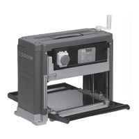
COMPONENTS AND CONTROLS (PIC.1)
1 Top cover 10 Guide roller
2 Planing height adjustment handle 11 Transport handle
3 Side cover 12 Rollerhousing
4 Depth scale 13 In feed roller
5 Stop/StartandEmergencystop 14 Hex key
6 Motor housing 15 Open end spanner
7 Brush housing 16 Spare drive belt
8 Planer bed 17 Push stick
9 Mounting bolt hole
SPECIFIC SAFETY INSTRUCTIONS
WARNING!
SomewoodandwoodtypeproductsespeciallyMDF(Medium
DensityFibreboard)canproducedustthatcanbehazardousto
yourhealth.Werecommendtheuseofanapprovedfacemask
withreplaceablefilterswhenusingandcleaningthismachine.
Ensure that the machine is disconnected from the power supply
beforecarryingoutanyadjustmentsormaintenance.
Before turning the machine on for the first time ensure that the
bladesareinstalledcorrectly.
Allowthemachinetorunuptofullspeedbeforecommencing
anyplaning.
Observethemachineforexcessivevibration.
This could indicate a poorly installed blade or out of balance
cuttinghead.
Neverleavethemachinerunningwhileunattended.
Always allow the machine to come to a complete stop and
disconnect from the power supply before leaving the machine
unattended.
Alwayswearsafetygoggleswhenoperatingtheplaner.
Neverusethemachinewithoutthesafetyguardsinposition.
Nevermakepassesgreaterthan2.5mmindepth.
Ensure that the work piece is free from any nails or other foreign
objectsthatcoulddamagetheplanerblades.Donotusework
piecesthatare:shorterthan355mm,narrowerthan19mmor
widerthan254mmorlessthan25mmthick.
Never insert your fingers into the dust chute for any reason
whilethemachineisinoperation.Thecuttingbladesrevolve
atveryhighspeeds.
Position yourself by the side of the machine in such a way that
the operation can be carried out without having to over reach or
repositionduringoperation.Installthemachineonastablelevel
surfacebeforeoperation.
LOCATION
WARNING!Thismachineshouldnotbeused“freestanding”.
When deciding on a suitable location for this machine
consideration must be given to the maximum length of material
tobeplaned.Thereshouldbeenoughclearancetoallowthe
work piece to be fed into the machine safely and sufficient
clearance at the out feed end of the machine to allow the work
piecetoberemovedsafely.Thismachinemustbemountedon
a solid stable workbench using 10mm hex Nuts and Bolts of a
suitable length to ensure secure fastening to your workbench
(Pic.2).
ASSEMBLY (PICS.3&4)
Attachtheheightadjustmenthandletothepinonthetopcover
ofthemachineandtightenthecrossheadbold(Pic.3).Ensure
that the in feed and out feed rollers are positioned correctly
andarefreetorotate(Pic.4).Ifauxiliarysupportrollersareto
be used, they should be positioned at the correct height, and
approximately half the length of the material being planed, away
fromtheinfeedandoutfeedsideofthemachinee.g..Ifthe
materialbeingplanedis3mtrlong,theauxiliarysupportrollers
shouldbepositioned1.5mtrfromtheinfeedandoutfeedside
ofthemachine.
STARTING AND STOPPING (PIC.5)
NO VOLTS EMERGENCY STOP SWITCH
Thismachineisfittedwitha“NoVoltsSwitch”.Intheeventof
a mains power failure or if the mains plug is removed from the
mainssupplysocketbefore themachineis switchedoff.The
machinewillnotre-startwithoutwarningwhenthemainssupply
is restored or the mains plug is re-connected to the mains
supply,untilthemachineisswitchedONattheON/OFFswitch
fittedtothemachine.Theswitchisalsofittedwithanemergency
stopcover.Tostartthemachine,lifttheemergencystopcover
(Pic.5)(5.1)andpressgreentheONbutton(Pic.5)(5.2).Tostop
themachine,presstheredOFFbutton(Pic.5)(5.3).Intheevent
ofan emergency, hitthe emergencystop cover(Pic.5) (5.4),
this will switch the machine OFF and will mechanically lock the
emergency stop cover in place preventing the machine from
beingswitchedonuntilthemechanicallockhasbeenreleased.