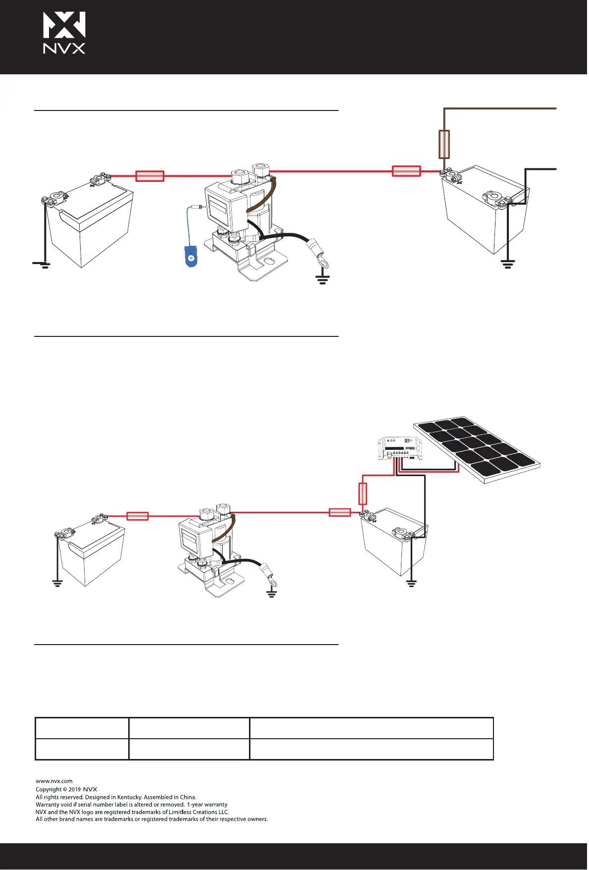
STANDARD WIRING DIAGRAMS
DUAL SENSING SMART BATTERY ISOLATOR
FAULT INDICATION
Dual Sensing Smart Battery Isolators monitor both the start battery and the auxiliary. If the
unit detects that either battery has exceeded 13.2 volts, then the isolator will be connected.
The benefit of the dual control enables the user to charge the main battery from a solar
panel or battery charger on the auxiliary battery.
The LED may stay ON for a period after the vehicle is turned OFF. Should a fault occur, the
LED on the manual switch is set to notify the operator of the fault. The LED will flash with the
following sequences:
Start
Battery
Fuse Fuse
Circuit
Breaker
Solar
Panel
Auxiliary
Battery
Smart Battery Isolator
Start
Battery
Load
Circuit
Breaker
Auxiliary
Battery
Loads
Fuse
Fuse
Manual
Switch
Smart Battery Isolator
+
+
+
-
-
-
Code 1 2 flashes Over-Voltage > 15.5 V
Code 2 3 flashes Voltage drop < 12.7 V
NVX.COM
Smart Battery Isolator Manual
XSBi80/XSBi200/XSBi500
 Loading...