17
V)
VPE 55
OTP Programming Voltage
VDDC 56
digital supply to core (3.3 V)
OSCGND 57
oscillator ground supply
XTALIN 58
crystal oscillator input
XTALOUT 59
crystal oscillator output
RESET 60
reset
VDDP 61
digital supply to periphery (+3.3 V)
P1.0/INT1 62
TV/AV (AV1) / AV2 /S-VHS mode Output.
P1.1/T0 63
TV/AV (AV1) / AV2 /S-VHS mode Output.
P1.2/INT0 64
Remote control signal input.
Note
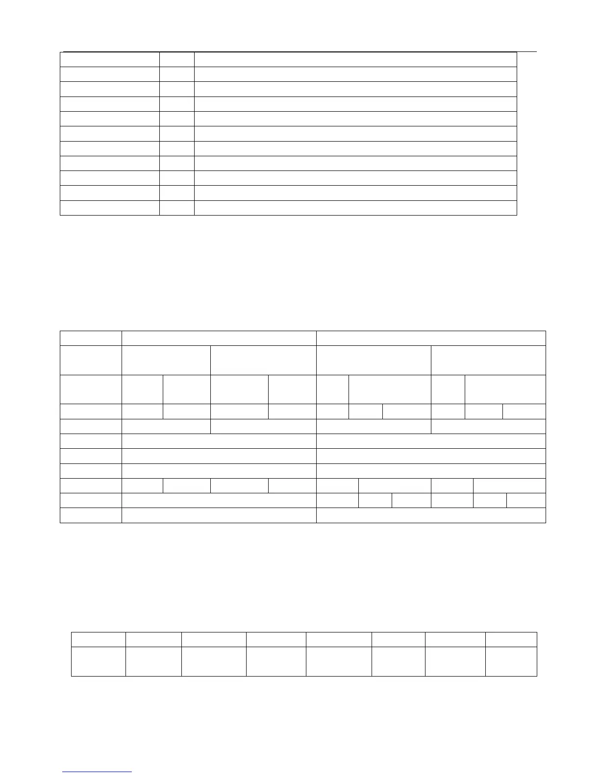
1. The function of pin 20, 28, 29, 31, 32, 35 and 44 is dependent on the IC version (mono intercarrier FM demodulator
/QSS IF amplifier and East-West output or not) and on some software control bits. The valid combinations are given in
table 1.
2. the vertical guard function can be controlled via pin 49 or pin 50. the selection is made by means of the
IVG bit in subaddress 2BH.
TABLE 1
IC version FM-PLL version QSS version
East-West
Y/N
N Y N Y
CMB1/CMB0
bits
00 01/10/11 00 01/10/11 00 01/10/11 00 01/10/11
AM bits
- - - - - 0 1 - 0 1
Pin 20
AVL EWD AVL EWD
Pin 28 AUDEEM SIFIN1
Pin 29 DECSDEM SIFIN2
Pin 31 SNDPLL SIFAGC
Pin 32
SNDIF(1) REFO(2) AVL/SNDIF(1) REFO(2) AMOUT REFO(2) AMOUT REFO(2)
Pin 35
AUDEXT AUDEXT QSSO AMOUT AUDEXT QSSO AMOUT
Pin 44 AUDOUT Controlled AM or audio out
Note
1. When additional (external) selectivity is required for FM-PLL system pin 32 can be used as sound IF input.
This function is selected by means of SIF bit in subaddress 28H.
2. the reference output signal is only available for the CMB1/CMB0 setting of 0/1. for the other settings this pin is
a switch output(see also 5 table 67).
Pin No. 6: Control keys input voltage
AN17821A/17823A Function : audio output
Function POWER MENU TV/AV V- V+ P- P+
Voltage 11/16-
13/16VDD
9/16-
11/16VDD
7/16-
9/16VDD
5/16-
7/16VDD
3/16-
5/16VDD
1/16-
3/16VDD
0-
1/16VDD
 Loading...