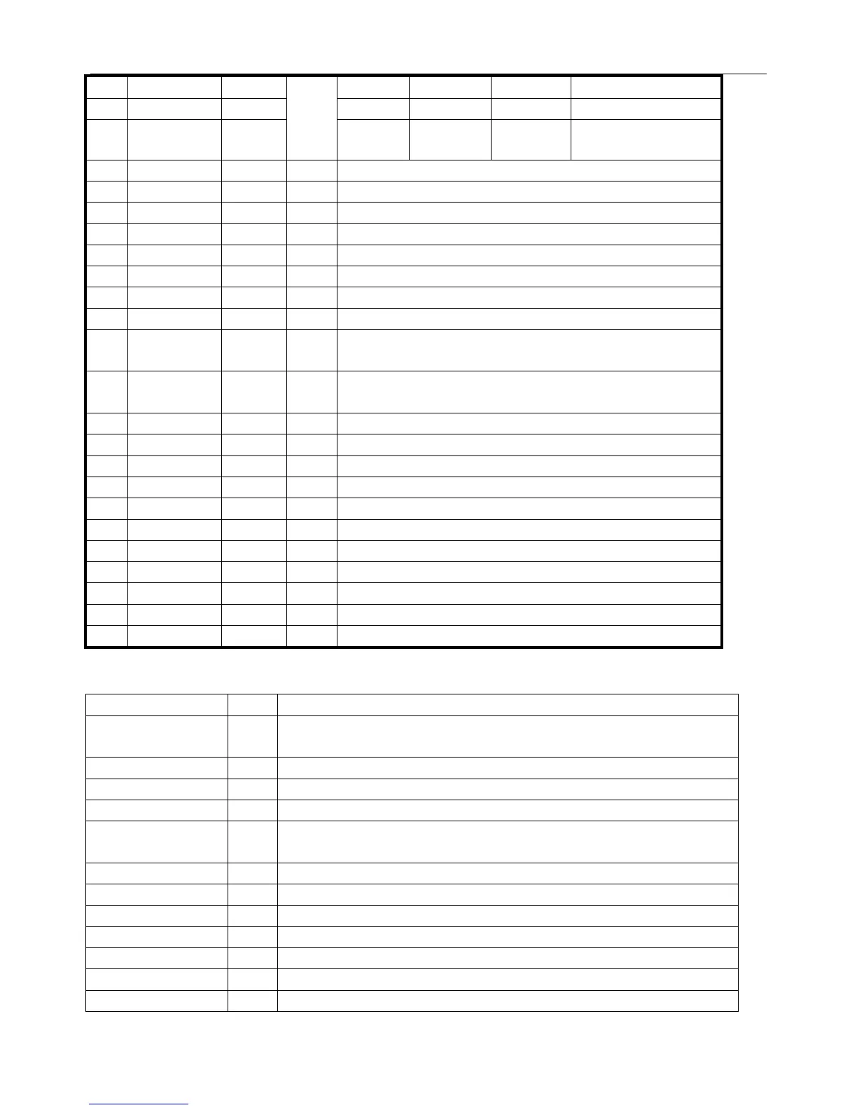
15
VHFL 1 0 0
VHFH 0 1 0
Band
opt=2/
band
3
UHF 1 1 1
FST BAND ON/OFF OFF OFF:TABLE1;ON:TABLE2. NOTE*
FST LH Frequency of H band setting*
FST HU Frequency of U band setting*
SECAM ON/OFF ON SECAM system option
DK ON/OFF ON Sound system option
I ON/OFF ON Sound system option
M ON/OFF OFF Sound system option
BG ON/OFF ON Sound system option
AUTO
SOUND
ON/OFF ON Sound system auto indefine for auto search
SIFPREFER DK/I/BG/
M
BG Perfer sound system for auto search
S8 SUB CON 0~63 32 Subsidiary contrast setting
SUB BRI 0~63 32 Subsidiary brightness setting
SUB COL 0~63 32 Subsidiary color setting
SUB SHA 0~63 32 Subsidiary sharp setting
SUB TINT 0~31 16 Subsidiary tint setting
YDLY PAL 0~15 2 Y delay time setting of PAL
YDLY NTSC 0~15 2 Y delay time setting of NTSC
YDLY AV 0~15 2 Y delay time setting of AV
CATHE 0~15 8 Cathode drive level of CRT
SC.BRI 0~63 8 Brightness of the single horizontal line mode
PWL 0~15 15 Limit of peak of white level
5. ICs functional description
UOC TDA93XX/83XX
SYMBOL PIN DESCRIPTION
STAND BY output. 1 In STAND BY mode, high level (Power OFF).
For Power ON this pin will be reduced to low.
SCL 2 I
2
C-bus clock line
SDA 3 I
2
C-bus data line
TUNING 4 tuning Voltage (Vt) PWM output
P3.0/NTSC SW 5 Port 3.0 or NTSC output/SCART SW input, Forced NTSC selection,
Low-level output, otherwise High output.
KEY 6 Control keys input *3
VOL 7 Sound Volume control PWM output
MUTE 8 Sound mute output
VSSC/P 9 Digit ground for μ-controller core and periphery
BAND1 10 Tuner Band selection output
BAND2 11 Tuner Band selection output
VSSA 12 Analog ground of teletext decoder and digital ground of TV-processor
 Loading...