Do you have a question about the NXS NX1000.1 and is the answer not in the manual?
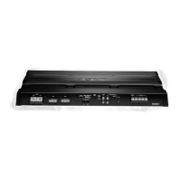
Congratulations on purchasing a NXS amplifier with digital signal processing.
Proper installation maximizes performance; consider an authorized retailer.
Control amplifier DSP via PC with NXLI and NXCS software for real-time adjustments.
Optional DIN-sized controller for PC-free setup, adjustment, and preset recall.
Intelligent remote control for hands-on adjustment of amplifier output levels.
Fuse power wire within 6" of the battery to protect the car's electrical system.
Utilize high-grade barrier spades and terminal rings for secure connections.
Route wires under carpet/side panels, away from electrical wires and sharp edges.
Mount amplifier carefully, avoiding vehicle wires, lines, and the gas tank.
Keep ground wires short, at a common point, and ensure a clean connection.
Built-in DSP for advanced control of gain, crossover, tone, and time delay.
Includes DC Offset, Short Circuit, and Thermal protection for amplifier safety.
Combines two amplifiers of the same model for doubled output power.
High Level Input with Remote Auto Sensing and Power/Protect indicator LEDs.
Provides full range line outputs for connecting additional amplifiers.
Internal fusing protects against short circuits and excessive current.
Automatically turns the amplifier on/off with the head unit's remote output.
Fine-tunes level matching between source and amplifier for optimal performance.
Select a location with adequate ventilation and avoid vehicle hazards.
Connect amplifier's +12V to battery terminal with an inline fuse.
Connect amplifier's GND terminal to a clean chassis point with a short cable.
Connect REM terminal to head unit's remote output or switched +12V.
Connect amplifier's +12V to battery terminal with an inline fuse.
Connect amplifier's GND terminal to a clean chassis point with a short cable.
Connect REM terminal to head unit's remote output or switched +12V.
Connect amplifier's +12V to battery terminal with an inline fuse.
Connect amplifier's GND terminal to a clean chassis point with a short cable.
Connect REM terminal to head unit's remote output or switched +12V.
RCA signal connections for NX1000.1 and NX2000.1 amplifiers.
RCA signal connections for NX200.2, 400.2, and 500.1 amplifiers.
Signal connections for NX400.4 using two-channel input configuration.
Signal connections for NX400.4 using four-channel input configuration.
Signal connections for NX900.5 using two-channel input.
Signal connections for NX900.5 using four-channel input.
Signal connections for NX900.5 using five-channel input.
Connect to factory radios via high-level inputs for specific amplifier models.
High-level input connections for NX400.4 with floating ground radios.
High-level input for NX900.5 (2-channel) with floating ground radio.
High-level input for NX900.5 (4/5-channel) with floating ground radio.
Diagram and cautionary notes for connecting speakers to the NX500.1.
Diagram and cautionary notes for connecting speakers to NX1000.1/NX2000.1.
Speaker connection diagrams for NX200.2 and NX400.2 amplifiers.
Speaker connection diagrams for the NX400.4 amplifier.
Diagram and cautionary notes for connecting speakers to the NX900.5.
Configure amplifier addresses using dip switches for networking and control.
Example of connecting NXLCDC to NX400.4 for coordinated amplifier adjustments.
Example of sharing a DSP Netlink address between NX1000.1 amplifiers.
Connect two identical amplifiers for doubled output power in Power Bridge mode.
Use NXLCDC or NXLC to remotely control amplifier output levels for specific channels.
Guide to setting input gain for optimal level matching and distortion-free output.
Diagnose and resolve issues causing no audio output from the amplifier.
Address causes and solutions for reduced audio output levels.
Identify and fix engine noise or electrical interference in the audio system.
Steps to resolve issues when the amplifier's protection LED is lit.
Detailed specifications for NX200.2, NX400.2, NX400.4, and NX900.5 amplifiers.
Detailed specifications for NX500.1, NX1000.1, and NX2000.1 amplifiers.
| Power Output (RMS) | 1000W |
|---|---|
| Number of Channels | 1 |
| Input Sensitivity | 0.2V - 6V |
| RMS Power at 1 Ohm | 1000W |
| Signal to Noise Ratio | 90dB |
| THD | 0.1% |
| Subsonic Filter | 10Hz - 40Hz |
| Bass Boost | 0 - 12dB |