Items necessary for starting
Tools, accessories, etc.The following items are necessary
for operating the engine.
BEFORE STARTING
Battery leads
Electric starter and starter battery
Hexagon starting shaft
Glowplug battery
Fuel
Fuel Filter
Fuel Pump
Silicone Fuel Line
TOOLS
Screwdriver
Phillips Screwdriver
Socket Drivers
Hex Drivers
End Wrenches
Needle Nose Pliers
0.S. SPEED Plug Wrench (optional extra)
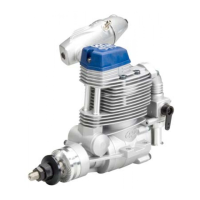
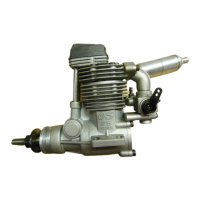
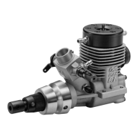
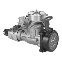
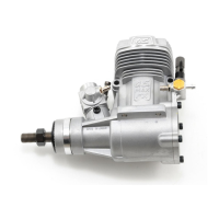
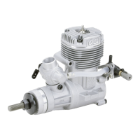
INSTALLATION OF THE ENGINE
Make sure that only the under-surfaces
of the engine’s mounting lugs are in
contact with the engine mount.
INSTALLING THE GLOWPLUG
Install washer on glowplug and insert carefully into
Heatsink-head, making sure that it is not cross-threaded
before tightening firmly.
INSTALLATION OF THE CARBURETOR
INSTALLATION OF THE STANDARD ACCESSORIES
CARBURETOR CONTROLS
O.S. Super Filter (Fuel Can Filter)
The under-surfaces of all O.S. engine beam mounting
lugs are precision machined flat and exactyly parallel
to the engine's horizontal axis. It is essential that the
engine mounts in the model are also accurately made
and aligned. If they are not, they will cause stress and
distortion within the engine itself, probably resulting in
loss of performance and internal damage.
The recommended screws for securing the engine to
the engine mounts in the model are 3mm or 4-40 steel
Allen type. It is also advisable to use lock washers or
LOCTITE to prevent nuts from loosening.
Select, by practical tests, the most suitable fuel from
among the best quality fuels available in your country
for helicopter use. For the best throttle response, a fuel
containing 10% to 30% nitromethane is preferable.
Lubricants may be either castor-oil or a suitable
synthetic oil (or. a blend of both) provided that they are
always of top quality. For consistent performance and
long engine life, it is essential to use fuel containing AT
LEAST 18% lubricant by volume. Some fuels
containing coloring additives tend to deterriorate and
may adversely affect running qualities. If in doubt
compare to a fuel known to be good.
1.
2.
Retainer screw
Carburetor Rubber Gasket
0.2mm gap
Insert the carburetor rubber gasket on the carburetor
body securely.
Then, insert the carburetor in the crankcase.
Rotate the retainer screw gently until it stops, then
tighten a further 90-120 degrees.
Do not over-tighten the screw as this will damage the
Carburetor Body.
3.
Loosen carburetor retainer screw slightly.
As delivered, the engine has its carburetor lightly
fitted into its intake boss. Secure it as follows.
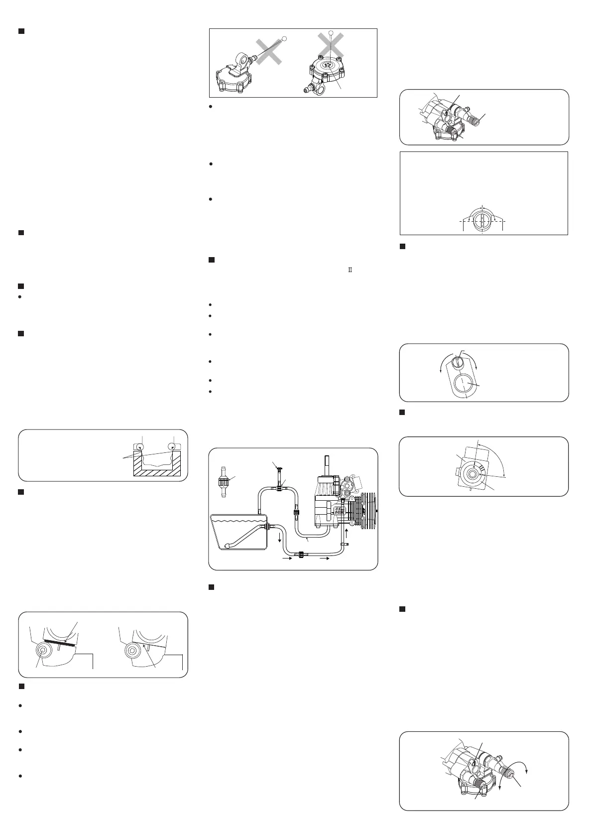
CARE OF REGURETOR
NEVER disassemble the pressure regulator.
Their original performance may not be restored after
reassembly.
NEVER insert anything into the inlet nipple in an
attempt to clear a suspected obstruction.
DO NOT allow foreign matter to enter the fuel
system. Dirt inside the regulator, no matter how
small, may obstruct the flow of fuel and prevent a
from working properly.
DO NOT block the five holes on the top of the
regulator, or the regulator may not work properly.
Do not insert a needle or anything into these holes.
ABOUT THE REGURETOR
Five holes
ALWAYS use fuel filters.
Keep the fuel tank scrupulously clean and filter all
fuel as it enters the tank (e.g.via an O.S.'Super-Filter'
Code No.72403050) and use a good quality in-line
filter between the tank and regulator. Remember to
inspect filter screens at regular intervals and rinse
clean as necessary.
DO NOT clean the regulator with organic solvent
such as kerosene, light machine oil, gasoline,
thinner or crc as the silicone rubber parts inside will
deteriorate. Be sure to use methanol or fuel.
DO NOT allow fuel to remain in the regulator.
After finishing the day's flight session, be sure to run
out the fuel in the regulator. Stop the fuel flow to the
regulator with a stopper and run the engine at idle to
use up the fuel in the regulator. After stopping the
engine, rotate the engine by electric starter to
eliminate fuel inside the engine.
It is suggested to use the O.S. Power Boost 55 silencer
which is developed to best Match the 55HZ-R.
Carry out plumbing referring to the instructions
supplied with the silencer.
ABOUT THE SILENCER AND PLUMBING
Carry out plumbing referring to a sketch.
Connect silicone tubing cut into approx. 10cm to the
nipple on the cover plate.
Then, connect the check valve supplied with the
engine as sketched (Be aware of the direction.) It is
suggested to install a stopper as shown in the sketch.
When refueling, remove this stopper to release
pressure in the fuel tank.
Connect the fuel line to the nipple on the regulator.
Be sure to equip a commercially available in-line filter
to avoid dust entering the regulator.
Note:
Since the muffler pressurized fuel feed is not used
with this engine, plug the nipple on the muffler or
replace it with a bolt.
Fuel tank
Fuel Stopper
(commercially
available)
Fuel Filter
(commercially available)
Check valve
Check valve
Fuel Stopper
(commercially available)
T Nipple
Remove when refuelling
(commercially
available)
Be aware of
direction
Grooved part should
face the fuel tank.
Silicone tubing
approx.10cm
(commercially
available)
With a fixed-wing model, power failure is rarely a
serious threat to the safety of the aircraft since it can
usually glide down to a safe landing. In a helicopter,
on the other hand, it is vitally imporant that the engine
keeps running and that there is a quick and reliable
response to the throttle in order to ensure safe ascent
and descent of the model.
The High-Speed (Main) Needle Valve
When set to produce maximum power at full throttle,
this establishes the basic fuel/air mixture strength.
This is then maintained by the carburetor's
automatic mixture control system to cover the
engine's requirements at reduced throttle settings.
The Idle Mixture Control Screw
This provides the means of manually adjusting the
mixture control valve. By setting the Mixture Control
Screw for the best idling performance, the mixture
control valve automatically ensures that fuel is
accurately metered to maintain the correct mixture
strength as the throttle is opened.
Three adjustable mixture controls are incorporated in the
Type 40L-R. They are as follows.
A
B
The Medium Speed Needle Valve
This is an extra control that can be brought into
play, if necessary, after adjusting A and B above. It
provides the means of fine-tuning mixture strength
over that all-important part of a helicopter's throttle
range where the model is flying in, or near, the
hovering mode.
C
Idle MIxture Control Screw
High Speed Needle Valve
(Main Needle)
Medium Speed Needle Valve
NOTE
90 degrees
90 degrees
As the idle mixture control screw is installed with
LOCTITE, it may initialy feel stiff, and it is suggested to
use a slightly oversized screwdriver. The screw can be
turned only 90 degrees either way. Do not force to turn
further, or it may break or cause trouble.
BASIC POSITION OF MIXTURE CONTROL SCREW
(Mixture Control Valve)
Rich
Mixture Control Valve
MIxture Control Screw
Lean
As delivered, the Mixture Control Screw is positioned at
approximately the center as shown in the sketch. Mixture
gets lean when the Mixture Control Screw is turned right,
while mixture gets rich when the Mixture Control Screw is
turned left.With a model helicopter, adjustments vary with
combined various factors such as climatic conditions,
fuel, muffler, main rotor, weight of the model, gear ratio,
etc. Therefore the Mixture Control Screw position varies
with each model and set- up, and it is normal if the Mixture
Control Screw position is off the center.
89 degrees
When the triangle mark on the carburetor rotor meets
the far right mark, the throttle is fully closed. When the
triangle mark meets the top mark, the throttle is fully
open. The range is 89 degrees. You may use the other
three marks as the reference marking of throttle
opening to your preference when hovering.
WARNING!
Never try to check the triangle mark position while
the engine is running and rotor is rotating, or you
may be hit by rotating rotor which results in serious
injury. Stop the engine and rotor before checking
the triangle mark position.
Carburetor Rotor
Carburetor Body
Fully closed
position
Fully opened position
As shown in the sketch, the carburetor has graduation
marks.
GRADUATIONS ON THE CARBURETOR BODY
Note: In case it is hard to insert the carburetor in
the crankcase. Do not force it, or damage to the
crankcase can occur.
(optional extra)
Be sure to use an electric starter to start the engine.
Fill the fuel tank with fuel. When filled, prevent the
fuel from flowing into the carburetor with a
commercially available fuel stopper, etc.
Release the stopper before starting the engine.
1.
2.
Starting procedure is as follows:
Make sure that plug element glows red, and install
the plug in the cylinder head.
STARTING
Open
1.
Opening and closing of the Needle-Valve
Turn the needle clockwise to close the needle-valve,
and turn the needle counter-clockwise to open the
needle-valve as shown in the sketch.
Close
High Speed
needle-valve
Idle Mixture Control Screw
Medium Speed needle-valve
 Loading...