EasyManua.ls Logo

Oasis VERSACOOLER II Series User Manual

Oasis VERSACOOLER II Series
26 pages
To Next Page IconTo Next Page
Page #1 background imageLoading...
Page #1 background image
OASIS
®
VERSACOOLER
®
II MODELS
PACSL, P8ACSL, P8ACSLEE, PF8ACSL, PF8ACSLEE, PV8ACSL, PVF8ACSL, PGACSL, PG8ACSL
SUNROC MODELS ADA8ACB, ADA8ACBHF, ADAF8ACB, ADAF8ACBHF
INSTRUCTIONS
A. INSPECTION
Inspect the water cooler, water fountain and cartons for evidence of rough handling and concealed damage. Damage claims should be filed with the
carrier.
B. TO PUT WATER COOLER AND FOUNTAIN INTO SERVICE
1. NOTE: The following states require a licensed plumber to install cooler; AG, GA, MA, MI, OK, RI, SC, SD, TX, VT and WI.
CA, KS, MN, NM and OR allow for a state-registered installer or contractor as well. State and local plumbing codes may prohibit the use of
saddle tapping valves for water line connection in some applications. All connections must conform to applicable plumbing codes.
2. The P8ACSL/ADA8ACB is composed of a water cooler and a water fountain. The water cooler contains the refrigeration system and is
always mounted on the right side. This unit can be configured with the water cooler high or low. Refer to the proper roughing in drawing for
location of plumbing and electrical service.
3. FLUSH BUILDING WATER SUPPLY BEFORE INSTALLING UNIT.
4. Install wall hangers as shown on the desired roughing in drawing. Wall hangers are shipped fastened to the backs of the unit. Units with
factory installed filters have additional instructions on a label inside of the access panel. Read these before installing the unit.
5. To configure this cooler for right side high or right side low installation, refer to the details below. The bottom screws of the
appropriate side panel may be temporarily removed to install the patch plate. Assemble the drains as shown below, matching the
position of the gaskets to the contour of the cooler tops.
6. Mount the water cooler on the right hanger.
7. Straighten the inlet “Water In” tube in the water fountain. Mount the water fountain on left side hanger while routing the “Water In” tube
through the access hole to the water cooler. Remove the plug from the “Drain/Remote Cold Water” connection and insert the “Water In” tube.
8. All provided waste drain parts for field installation are packed in the water fountain. Assemble the drain per the appropriate
roughing in drawing. The short leg of the crossover piece will be on the water cooler side. When the unit has an internal waste trap,
the trap should be wrapped with insulating tape to prevent sweating. The use of the 1-3/4” knockout for a waste line is not
recommended because of a potential conflict with ADA* toe space requirements. Check with your local building code inspector for
approval.
9. Install a shut off valve in water supply line. Remove the strainer from the cooler “Water Supply” tube. Solder 3/8” inlet tube extension
(furnished) with lead free solder to “Water Supply” tube and insert the strainer in open end of extension. Connect extension to shut off valve.
To allow access to strainer for service, this connection should not be a solder or flare joint. To ease removal of the strainer, a sheet metal
screw may be lightly threaded into the open end.
10. Rotate the fan blade by hand to see that it is free of obstructions.
11. Check the available power supply against the water cooler data plate to assure correct electrical service. Plug power supply cord into wall
outlet. The rear most 1-3/8 diameter knockout in the frame bottom is for an externally located electrical supply. Make sure the knockout hole
edge is smooth and free of any burrs. Use of a Heyco busing #2184 in the knocked out hole is recommended in order to prevent damage to the
service cord and to close up excess opening around the cord. Route the cord so it does not interfere with ADA* space requirements.
12. To fill the cold water tank on the water cooler, open the water supply line shut-off and push any one of the front pushbuttons to allow water to
flow to the bubbler. On The EE model, actuate the solenoid by holding one hand approximately 3 inches from the infrared sensor. Run water
until stream is free of bubbles.
13. To adjust bubbler stream:
a) All pushbutton models are equipped with a cartridge regulator. The P8ACSL/ADA8ACB and PF8ACSL/ADAF8ACB have a slot in the
shelf below the pushbuttons. Insert a screwdriver in this slot to adjust regulator. Turn adjustment clockwise to increase stream height.
To access PV8ACSL and PFV8ACSL adjustment, remove the bezel and button from the front of the cooler.
b) Electric eye (EE or HF) models have a regulator built into the bubbler. If adjustment is needed, insert a 5/64 wrench approximately 1-
1/8" into the bubbler nozzle opening until it bottoms out and is seated in an adjust screw. Turn the adjust screw clockwise to reduce the
stream height or counterclockwise to increase the height. Note, less than one turn is required to go from a closed to a wide open flow.
Do not overtighten the adjuster in the closed position as stripping the hex impression in the adjust screw may result.
14. To adjust the beam range of the sensor (EE or HF models only):
a) Shut off the water and power supplies.
b) Remove the two screws from the top front.
c) Remove the eight screws from the bottom of the nose that holds the nose to the shelf.
d) Remove the nose to gain access to sensor adjusting screw located between the two lenses.
e) The screw can be turned a maximum of ¾ turns. Turn screw counterclockwise to decrease range. The sensor has an adjustable range of
24” to 48”. It is factory set at 27”. There is a non-adjustable on-time delay of .75 seconds to prevent nuisance actuation of the solenoid
valve should someone walk by. After drinking, the water will shut off immediately after walking away. Maximum run time is 30
seconds should someone tamper with the sensor. NOTE: Walls with a reflective finish, i.e., ceramic tile, across from the sensor may
cause false actuation no matter what the sensor adjustment is for distance. Therefore, do not install the unit in such an area or dull the
surface of the wall so it will not reflect light.
C. MAINTENANCE
The only maintenance operation required is the removal of dirt and lint from the condenser of the water cooler. Inspection should be made at 3-
month intervals. Disconnect the power supply cord, then clean the condenser with a small stiff non-wire brush when required. Observance of this
procedure will ensure adequate air circulation through the condenser so operation is efficient and economical.
Question and Answer IconNeed help?

Do you have a question about the Oasis VERSACOOLER II Series and is the answer not in the manual?

Oasis VERSACOOLER II Series Specifications

General IconGeneral
ModelVERSACOOLER II Series
CategoryOutdoor Fountain
MaterialStainless Steel
Power SourceElectric
Voltage115V
Pump IncludedYes
Warranty1 Year Limited
OptionsFiltered
Water Flow8 GPH
ActivationPush-button

Summary

B. TO PUT WATER COOLER AND FOUNTAIN INTO SERVICE

Initial Setup and Plumbing

Covers state plumbing requirements, flushing, installing hangers, and connecting lines.

Filling and Adjustments

Procedures for filling the water tank and adjusting bubbler stream and sensor range.

C. MAINTENANCE

Condenser Cleaning

Periodic cleaning of the condenser with a brush to ensure efficient operation.

D. & E. COOLER PROTECTION AND LUBRICATION

Overload Protection

Explains the automatic reset protector for the compressor motor during overloads.

Lubrication Requirements

States the compressor is sealed and requires no lubrication; fan motor may need occasional oil.

F. TO DISCONTINUE USE

Draining and Disconnecting

Detailed steps for draining all water, disconnecting lines, and preparing for storage or freezing.

Prepare for Freezing/Shipping

Critical instruction to drain all water before freezing temperatures or shipping.

ROUGHING-IN AND DIMENSIONAL DRAWING

Right Side High Configuration Diagram

Diagram showing rough-in and dimensional details for the right side high configuration.

Installation Notes for Diagrams

Important notes regarding plumbing, electrical, ventilation, and ADA requirements for installation.

ROUGHING-IN AND DIMENSIONAL DRAWING (Right Side Low)

Right Side Low Configuration Diagram

Diagram showing rough-in and dimensional details for the right side low configuration.

Installation Notes for Diagrams (Right Side Low)

Important notes regarding plumbing, electrical, ventilation, and ADA requirements for installation.

Installation Instructions

VersaFiller Overview and Options

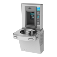
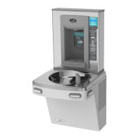
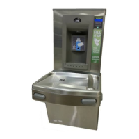
Overview of VersaFiller, its extension role, and water dispensing options.

Assembly and Combo Unit State

Notes on partial assembly and plumbing status of combo units.

Section 1: Getting Started

What's Included

Lists the components included with the VersaFiller kit.

Tools Required for Installation

Lists the necessary tools for installing the VersaFiller.

Section 2: Rough In Drawing

Rough-In Diagram (PAC/P8AC)

Rough-in and dimensional drawing for PAC/P8AC models with Hands-Free VersaFiller.

Installation Notes for Rough-In Diagram

Critical notes for installation including plumbing, electrical, ventilation, and ADA.

Section 2: Rough In Drawing (Split Level)

Rough-In Diagram (Split Level)

Rough-in and dimensional drawing for split level models with Hands-Free VersaFiller.

ADA Compliance for Split Level

Specific ADA guideline for mounting VersaFiller on the low unit in split level configurations.

Section 3: Installation

A: Drilling Hole for Water Line

Instructions for drilling a hole in the cooler top for the water line connection.

Prepare for Drilling

Steps include disconnecting power/water, positioning template, and marking location.

Drill Hole and Install Bushing

Procedure for drilling the 7/8" hole and installing a snap bushing for protection.

Hole Location Template Instructions

Template Alignment and Marking

Guides on aligning the template edges and marking the center for drilling.

Mark and Drill Hole

Mark the center, remove the top, and drill the 7/8" diameter hole.

Section 3: Installation (Water Line)

B: Connecting the Water Line

Instructions for connecting the water line to the VersaFiller.

Connect Tube (Single/Split Level)

Guides connecting the water tube for both single and split level VersaFiller ready coolers.

Tank Drain and Fitting Connection

Steps to remove the tank drain plug and insert the tube into the fitting.

Section 3: Installation (Water Line Connections)

Tee and Tubing Preparation

Information on tee/tubing packaging and cutting tubing for filter installation.

Water Line Routing and Connections

Guides routing and connecting water lines to dummy units and VersaFiller.

Section 3: Installation (Retrofit)

Retrofit Instructions and System Identification

Instructions for retrofitting and identifying cooling tank system types.

Locate Cooling Tank Tube and Diagrams

Steps to locate tubes and diagrams showing plastic/copper outlet tubes.

Section 3: Installation (P8AC Version)

Disconnect and Route Tubing

Disconnect tubing from valve elbow, route TEE assembly under waste drain.

Connect TEE Assembly

Connect the 6" length of tubing to the water valve elbow.

Section 3: Installation (P8AM Version)

Prepare Copper Outlet Tube

Remove tar tape, pull back insulation, and cut copper tube.

Install TEE and Connect Tubing

Install TEE fitting with copper tubing and connect plastic tubing to TEE branch.

Section 3: Final Installation Steps

Feed Tubing Through Top Bushing

Feed tubing, including white tube for single units, through the top bushing.

Attach Top and Route Cord

Attach the top to the cooler, ensuring flow switch cord passes through the bushing.

TIP: Front Nose Removal (P8AM)

Tip for easier connection on P8AM models by removing the front nose.

Section 3: Installation (Mounting)

C: Mounting Frame to Wall

Instructions for mounting the installation frame to the wall.

Position Rubber Gasket

Place the rubber gasket on the cooler top, centered and against the wall.

Section 3: Installation (Frame Mounting)

Position and Mark Frame

Set the wall frame on the gasket, center it, and mark hole locations for fasteners.

Secure Frame and Route Tubing

Secure frame to wall, ensuring tubing/wire is pulled through the frame hole.

Install Insulation and Connect Tubing

Slide insulation over water line and connect tubing to solenoid inlet.

Section 3: Installation (Cabinet Placement)

Place VersaFiller Cabinet and Route Cords

Place cabinet, feeding power and ground wires through bushing and ensuring gasket fit.

Attach VersaFiller Assembly

Secure the VersaFiller assembly to the frame using four torx screws.

Leave Top Cap Off

Instruction to leave the top cap off until programming is complete.

Section 3: Installation (Final Assembly)

Install Drip Tray and Grate

Install the drip tray and anti-splash grate using Phillips head screws.

Connect Power and Ground Wiring

Connect power supply terminals and attach the green ground wire.

Turn On Water and Check

Turn on water supply, check for leaks, and release trapped air.

Finalize Installation

Place the top cap back on and fasten with torx screws if installation is correct.

Section 4: Bottle Filler Electronics Set-up

Factory Default Settings

Lists the default program settings for the bottle filler electronics.

Accessing Pushbutton

Guides on removing top cap or panels to reach the pushbutton.

Changing Program Settings

General instructions on how to change program settings via the pushbutton.

Setting Dispense Parameters

Covers setting units, filter status, flow rate, counts, and dispense time.

Addendum: Pressurizing Cooling Tank

Safety Precaution: Power/Water Off

Safety instruction to turn off water and disconnect power before proceeding.

STEP 1 & 2: Unplug Water Lines

Unplug water line from valve inlet and tubing from cooling tank inlet.

Addendum: Pressurizing Cooling Tank (Steps 3-5)

STEP 3: Connect Tubing to Cooling Tank

Plug the un-insulated tubing into the quick-connect elbow leading to the cooling tank.

STEP 4 & 5: Connect Tubing to Valve

Unplug tubing from valve outlet and connect it to the valve's left side elbow.

Addendum: Pressurizing Cooling Tank (Steps 6-8)

Step 6 & 7: Reconnect Tubing

Unplug cooling tank outlet tubing and connect it to the valve's right side.

Step 8: Connect to Cooling Tank Top

Connect the tubing from step 4 to the quick-connect fitting at the top of the cooling tank.

Return to Water Line Connection

Instruction to return to the main installation section for connecting the water line.

EXPLODED PARTS BREAKDOWN

Parts List Details

Lists item numbers, part numbers, and descriptions for exploded parts breakdown.

Available Accessories

Lists optional accessories and their part numbers.

SET-UP GUIDE: Bottle Filler Electronics

Factory Default Settings

Lists the default program settings for the bottle filler electronics.

Accessing Pushbutton

Guides on removing top cap or panels to reach the pushbutton.

Changing Program Settings

General instructions on how to change program settings via the pushbutton.

Setting Dispense Parameters

Covers setting units, filter status, flow rate, counts, and dispense time.

Related product manuals