8.ENGINE
8-51
VALVE GUIDES
Valve Guide Inspection
Always replace valve stem seals
whenever valve guides are removed.
Measure valve guide in three places
using a small bore gauge.
NOTE: Clean valve guide to remove
carbon deposits before measuring.
Replace valve guide if it is out of
specification or has other damages
such as wear or friction surface.
VALVE GUIDE DIAMETER
(INTAKE AND EXHAUST VALVES
Removing the Valve Guide
Refer to following procedures in this
subsection to remove:
- Cylinder head
- Valves.
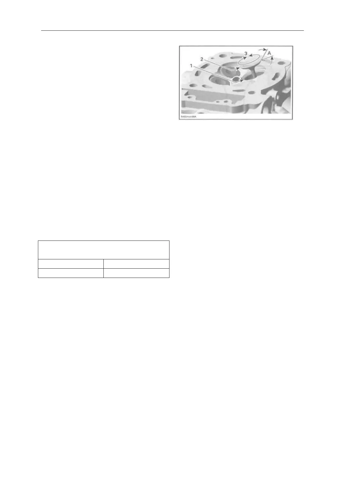
Apply some lapping compound to
valve face and
work valve on its seat with a lapping
tool.
1. Valve seat
2. Valve face (contact surface to valve seat)
3. Turn valve while pushing against cylinder head
A. Valve seat angle 45°
NOTE: Ensure to seat valves properly.
Apply marking paste to ease checking
contact pattern. Repeat procedure
until valve seat/valve face fits
together.
CYLINDER
Cylinder Removal
Refer to TUMING CHAIN subsection
and remove the following parts:
- Timing chain tensioner
- Camshaft timing gear.
Remove the cylinder head (see
CYLINDER HEAD in this
subsection).