PROGRAM
SWITCHES
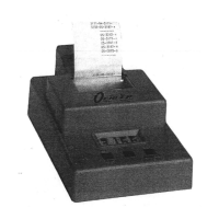
The programming switches for the Model
35P
are
normally set for
use
with
the four-foot rail.
The settings
of
the program switches control the M35. You can sele<;t
PRINTER
ON
or
OFF, EDIT
ON
or
EDIT
OFF,
and the screen spacing.
The
switches are inside next to the battery.
Remove the battery compartment
cover to see the switches. A pointed wooden stick
is
the best tool for
changing the switch settings, and a ballpoint pen is second choice.
The
first five switch positions (numbered I through 5) must match the
distance between the widest screens, measured center to center.
The
chart
below shows the switch settings for
each
spacing.
Ift
2ft
3ft
4
ft
Sft
6ft
7ft
8ft
SWI0N
OFF
ON
OFF
ON
OFF
ON
OFF
SW2 OFF
ON
ON
OFF
OFF
ON
ON
OFF
SW3 OFF OFF OFF
ON
ON
ON
ON
OFF
SW4 OFF
OFF OFF
OFF
OFF OFF OFF
ON
SWS
OFF
OFF OFF
OFF OFF
OFF OFF OFF
8ft
9ft
10 ft
11ft
12
ft
13ft
14
ft
15
ft
SWI OFF
ON
OFF
ON
OFF
ON
OFF
ON
SW2 OFF OFF
ON ON
OFF OFF
ON
ON
SW3 OFF
OFF
OFF OFF
ON
ON ON ON
SW4
ON
ON
ON
ON
ON
ON ON
ON
SWS
OFF OFF
OFF
OFF OFF OFF OFF OFF
Turning Switch 5
ON
multiples the screen spacing setting by 10,
or
causes
the displayed velocity to be multiplied
by
10.
For
example,
if
a precision air
rifle gives velocities near
570 fps, turning Switch 5 ON causes a readout
of
5714 instead
of
the expected 571.
The
5714
reading corresponds to 571.4
feet per second. This switch is most useful for work in metric units where
many velocities are under 999 meters
per
second and you want extra
resolution.
Page 4
Switch 6 controls the edit mode.
If
Switch 6 is ON, the edit
or
replay
function is available. In the edit mode, the unit will store the results
of
up to
20 shots. You can replay shots during
or
after the test and individual shots
can
be
omitted from the summary. With Switch 6 OFF, you can fire
and
summarize up to 255 shots.
We
ship the unit with the edit
mode
OFF.
Switch 7 is normally
ON
if you have a printer. You can turn the printer
OFF
to coax a few more shots from a weak battery
or
if
you are
out
of
paper. .
METRIC
VELOCITrES
For readout in metric units, the screen spacing should
be
set
at
an increment
measured exactly in meters.
One
meter is convenient,
hut
two
meters will
give better accuracy.
Use
any rigid metal tubing with a diameter slightly
less than 18 mm.
Cut
the tubing to 1.019
or
2.019 meters and
mount
the
sky screens flush with each end. This gives a spacing
of
1.000
or
2.000
meters between centers.
Set the distance switch as follows:
1m
2m
3m
SW1
ON
OFF
ON
SW2 OFF
ON ON
SW3 OFF OFF
OFF
SW4 OFF OFF
OFF
SWS OFF OFF
OFF.
Switch 5 can
be
turned
ON
if
aU
velocities will
be
less than
999
meters/second. This will cause readout in decimeters/second.
Page 5
 Loading...