Do you have a question about the Oerlikon CENTER TWO and is the answer not in the manual?
Covers manual applicability, catalog numbers, firmware versions, and type labels.
Details the controller's purpose, use with specific transmitters, and warranty conditions.
Outlines the differences between CENTER TWO and CENTER THREE models.
Covers personnel qualifications, danger symbols, and general safety instructions for operation.
Explains the location and importance of the mains disconnecting device for safety.
Provides overall data including mechanical specifications like dimensions and weight.
Details ambient conditions, operating modes, and mains connection requirements.
Lists voltage, frequency, power consumption, and connection type for power supply.
Details sensor connections, transmitter power supply, and measurement techniques.
Explains switching functions, including assignment, delay, adjustment, and hysteresis.
Details specifications for analog and recorder outputs.
Lists standard scope of delivery and available accessories.
Procedures for unpacking, checking for damage, and ensuring completeness of the unit.
Details methods for installing the unit as a desktop, panel, or rack-mounted device.
Provides specifications for mounting the unit within a control panel cutout.
Details the process for installing the unit into a standard 19-inch rack.
Explains the layout and function of connectors on the device's rear panel.
Instructions for connecting the power supply and establishing ground connection.
Describes sensor connection ports (RJ45, D-Sub) and pin assignments.
Details the RELAY connection, its purpose, and pin assignment.
Explains the CONTROL connection for analog outputs and HV-EMI signals.
Details the RS232C serial interface for remote control and firmware updates.
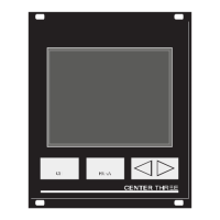
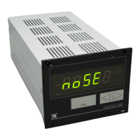
Identifies and explains the components and indicators on the controller's front panel.
Explains display indicators, units, and the function of control buttons (CH, PARA, Arrows).
Step-by-step guide for switching the controller on, off, and managing waiting times.
Explains Measurement, Parameter, and Program Transfer modes.
Describes display indications and status messages during measurement.
How to use control buttons to select channels and enter parameter mode.
How to manually switch the high-vacuum circuit and degas function ON.
How to manually switch the high-vacuum circuit and degas function OFF.
Method to display the type of connected transmitters on each channel.
Steps to enter and exit the parameter mode for configuration.
Lists available parameter groups for configuring the controller settings.
Step-by-step guide for selecting and modifying parameters within a group.
Details how to configure pressure-dependent switching functions for channels.
Explains terms like switching functions, threshold values, and hysteresis.
Step-by-step guide on how to assign and set threshold values for switching functions.
Defines the adjustable pressure ranges for lower and upper threshold values.
Lists parameters that vary based on the connected transmitter type.
Explains filter settings (Fast, Normal, Slow) to optimize signal quality.
How to configure the controller for different gas types and perform correction.
How to set the measuring range and manage offset correction.
How to activate and deactivate the degas function for specific transmitters.
Settings for switching transmitters ON (S-on) and OFF (S-off) with thresholds.
Sets switch-off thresholds and defines emission control rules.
Selects active filament and enables Pirani range extension.
Configure general settings like unit of measurement and baud rate.
Sets display digits and allows resetting parameters to factory defaults.
Details various logarithmic curves for recorder output based on transmitter type.
Describes specific logarithmic curves for combined transmitter measurements.
Specifies which errors trigger the error signal relay.
How to access the test parameter group for diagnostics.
Displays firmware version, watchdog control, and parameter setup lock options.
Procedures for performing RAM, EPROM, and EEPROM tests.
Procedures for testing the display, A/D converters, and I/O relays.
Verifies the functionality of the RS232C serial interface by echoing characters.
Explains the serial connection and terminology used for computer interface commands.
Defines the communication protocol, sending, and receiving procedures.
Illustrates common commands and how to handle syntax errors.
Explains number formats for data and continuous measurement transmission.
Provides a list of command abbreviations (mnemonics) and their meanings.
Continuation of the mnemonic list for various commands.
Configures the analog output mode and characteristic curves for recorder output.
Sets the baud rate and enables/configures continuous measurement transmission.
Configures correction factors for different gas types per channel.
Sets display digits and controls the degas function for transmitters.
Configures error relay allocation and displays current error status.
Controls emission, sets measurement filter, and defines full-scale ranges.
Selects the active filament and configures gas type correction for channels.
Controls high vacuum circuits and reads transmitter data strings.
Manages parameter setup lock and offset correction functions.
Displays offset correction values and the firmware version.
Retrieves transmitter readings and configures Pirani range extension.
Retrieves readings from all transmitters and resets the serial interface.
Saves current parameters to EEPROM, either default or user-defined.
Controls transmitter activation/deactivation and assigns switching functions to channels.
Reports the ON/OFF status of all configured switching functions.
Tests analog-to-digital converters and the display unit.
Performs tests on the EEPROM and EPROM memory modules.
Retrieves transmitter identification and tests I/O relays.
Tests the keyboard status and reports the status of all relays.
Configures Torr lock and tests the unit's RAM.
Tests RS232C, sets unit of measurement, and configures watchdog control.
Basic cleaning procedures and safety notes for mains power.
Detailed steps for preparing and performing a firmware update.
Instructions on copying, unpacking, and transferring firmware files.
Steps to restart the controller and verify settings after a firmware update.
Explains the necessity and process of precise calibration for accurate measurements.
Details the CAO command for setting calibration offsets for channels.
Details the CAF command for setting calibration factors for channels.
Step-by-step guide for automatically calibrating the unit using interface commands.
Explains how the controller indicates faults via display and relays.
Lists common error messages, their causes, and corrective actions.
Information on contacting technical support for persistent faults.
Recommends keeping original packaging and storing the unit in a dry room.
Outlines the need for proper disposal according to local regulations.
Table showing default settings for various controller parameters.
Lists related operating manuals and documentation for transmitters.
Alphabetical index of topics covered in the manual with page references.
| Digital Inputs | 8 |
|---|---|
| Digital Outputs | 8 |
| Analog Outputs | 2 |
| Protection Class | IP20 |
| Type | Controller |
| Communication Ports | Ethernet |
| Humidity | Max. 95% non-condensing |
| Storage Temperature | -20°C to +70°C |