EasyManua.ls Logo

OFFICINE OROBICHE PL Series User Manual

OFFICINE OROBICHE PL Series
7 pages
To Next Page IconTo Next Page
Page #1 background imageLoading...
Page #1 background image
OFFICINE OROBICHE S.p.A.
1/7
INSTRUCTION MANUAL FOR FLOW SWITCHES
PL SERIES
24010 Ponteranica (Bergamo) ITALY - via Serena, 10 - Tel. 0039/035/4530211 - Fax 0039/035/570546 - www.officineorobiche.it-e-mail:info@officineorobiche.it
*****************************************************************************************************************************************************************
JULY ’14 Information subject to change without prior notice IST/158-I
1.INSTRUMENT DESCRIPTION
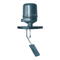
Flow switches PL series are designed to be mounted in an upright position along horizontal pipes.
These models are equipped with a tripping device, which can be equipped with single (SPDT) or double (DPDT) exchange
contacts for high or low flow rate control and/or alarms.
2. MODEL IDENTIFICATION
11 12 13 14 15 16 17 18 19 20
PL . . . . . . .
PNA
Aluminium
xx
Special
version
Finning
R3Ø R1 R4
Body material
SPDT
Ø 2
Contact type
PneumaticWater-proof
HG Bulb
A I J
Internal material/Paddle
VD
AISI 3162
M6
Water-proof
Golde- Contacts
Base
Current
Ermet.Sealed
with inert gas
Model
Water-proof
M4
EPWP
Ex-d
Case
M14
316
Direct
M2 M3
Acc 304
Contact
DPDT
Question and Answer IconNeed help?

Do you have a question about the OFFICINE OROBICHE PL Series and is the answer not in the manual?

OFFICINE OROBICHE PL Series Specifications

General IconGeneral
BrandOFFICINE OROBICHE
ModelPL Series
CategorySwitch
LanguageEnglish

Summary

Instrument Description

Model Identification

Operating Principle

Installation

Installation on the System

Details on mounting the flow switch in an upright position, ensuring pipe straightness and paddle clearance.

Wiring Connections

Instructions for connecting the flow switch terminal board, emphasizing proper grounding and secure housing cover.

Setting at Work

Calibration

Maintenance

Safety Warnings

Critical safety precautions before and during maintenance, including power disconnection and protective measures.

Paddle Routine Inspection

Procedure for inspecting and cleaning the paddle and rod assembly for wear, corrosion, or deposits.

Replacing the Paddle

Steps for removing and fitting a new paddle, followed by functional checks.

Contacts Inspection

Visual check of the tripping unit and micro-switch functionality, including manual magnet operation.

Replacing Switch Unit

Guide on replacing the switch unit and micro-switch, ensuring correct positioning and grub screw adjustment.

Setting Operation Point

Procedure for adjusting the switching unit to achieve the desired flow rate for alarm or control.

Dimensional Drawings

Case Drawings

Recommended Spare Parts

Troubleshooting

Disposal

Warranty and Returns

Returning Instruments

Guidelines for returning instruments for service, including required documentation and cleanliness.