Assembly Notes:
During assembly, hand tighten screw only when all screws
are in place, you may then tighten all screws completely.
CAUTION:
1. Do not use this chair as a step ladder.
2. Check for loose screws and tighten them every 6 months.
919-362-4765 (fax)
www.ofminc.com
161 Tradition Trail Holly Springs, NC, 27540
800-520-7471 (voice)
919- 303-6389 (voice)
support@ofminc.com
04.06.2010
A
AA-1 Adjustable Armrest
2 Units
B
M6x25mm Hex Screw
6 Units
C
Washer
6 Units
D
Wrench
1 Unit
Parts Listing
Model AA-1 Adjustable Arms
STOP
Assembly Instructions
Tools Needed: Phillips Head Screwdriver
Please read all instructions before assembly.
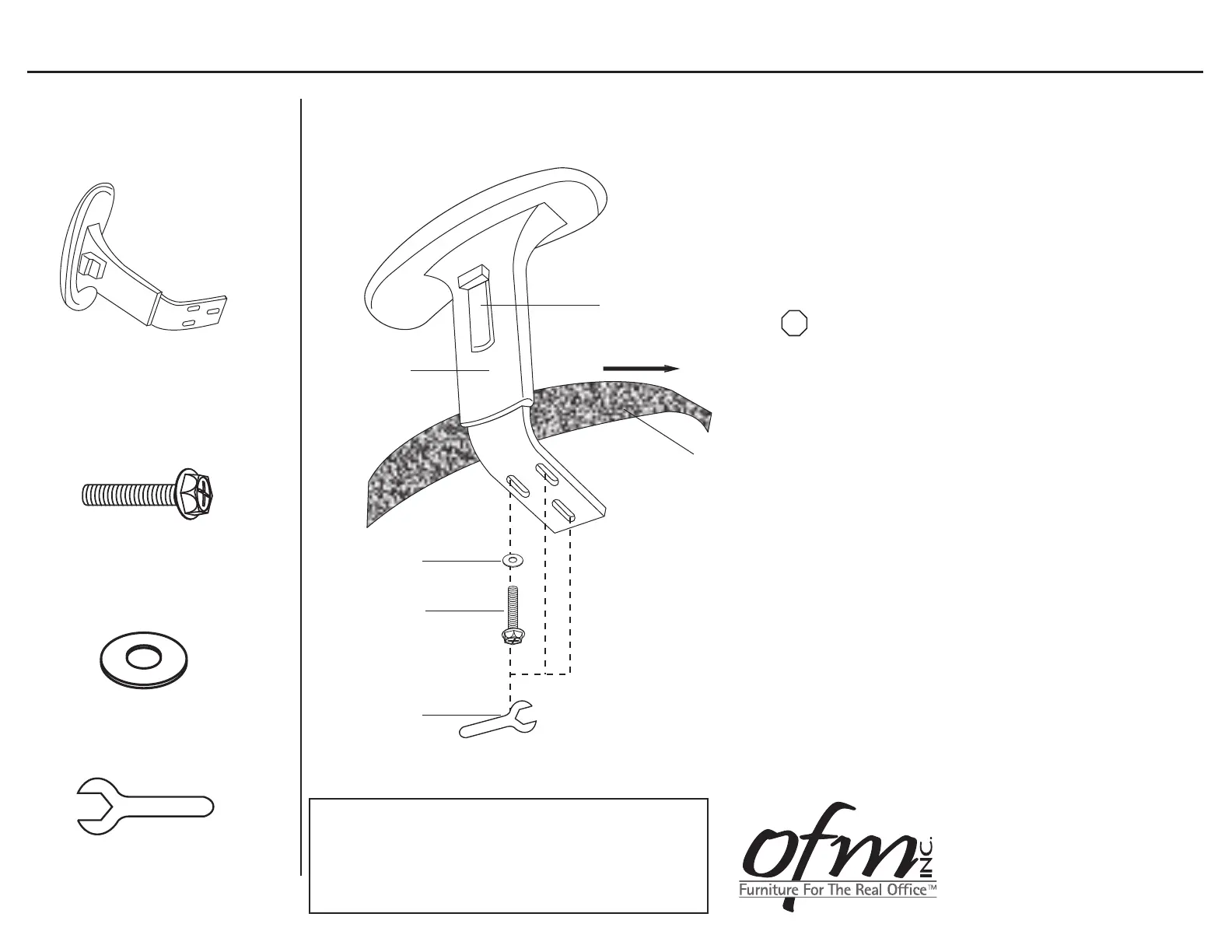
Step 1: Turn Chair Seat upside down and place on a
clean, non-abrasive surface.
Step 2: Align the pre-drilled holes in the Adjustable Armrest (A)
with the holes in the bottom of the Chair Seat,
making sure that the arms face the correct direction.
Step 3: Place three Washers (C) onto three M6x25mm
Hex Screws (B) and insert through the Armrest (C)
holes and into the Chair Seat.
Step 4: Tighten Screws (B) using supplied Wrench (D)
or screwdriver. It is recommended that to assure
screws are secure, a screwdriver is used to tighten.
To Adjust Arms:
Pull up on the Height Adjustment Button
and slide to desired height.
B
D
A
Chair Seat
Forward
Height Adjustment
Button
C
 Loading...