Do you have a question about the OilGear EPC 300 Series and is the answer not in the manual?
Secures EPC configuration from accidental changes via password protection.
Explains how the PC interface menu groups functions into logical Forms.
Configures password, mode, and communication setup parameters for the EPC module.
Covers the 12 pre-defined programs and their specific configuration settings.
Details settings for the Pump Controller, including HP limitation and stroke feedback.
Configuration options for Analog Inputs, Analog Outputs, and the Current Driver.
Configures advanced functions like Horsepower Limiting and Ramping.
Explains how diagnostics are represented using DAC counts, percentages, and voltages.
Describes front panel LEDs (Run/Fault, Valve Current, Feedback) for basic diagnostics.
Details diagnostic information accessible via the PC interface.
Lists diagnostic signals available for the programmable analog outputs.
Covers high priority faults and system messages indicating EPC status or errors.
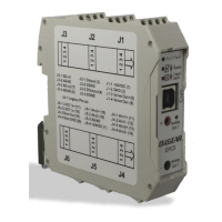
Provides a diagram and description of the EPC module's terminal pinout connections.
Lists key electrical, physical, and operational specifications for the EPC module.
Summarizes the digital and analog input/output capabilities of the EPC module.
Provides recommendations for cables and terminal specifications for system connections.
| Brand | OilGear |
|---|---|
| Model | EPC 300 Series |
| Category | Control Unit |
| Language | English |