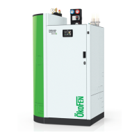
Installation Manual PELLEMATIC® SmartXS
1 Dear Customer ................................................................................................................................................ 5
2 Use only for the purpose intended ................................................................................................................ 6
3 General information ....................................................................................................................................... 7
4 Types of safety warning sign......................................................................................................................... 9
5 Warnings and safety instructions.................................................................................................................10
5.1 Basic safety instructions .............................................................................................................................. 10
5.2 Warning signs.............................................................................................................................................. 10
5.3 What to do in an emergency....................................................................................................................... 12
5.4 Installation with an existing boiler............................................................................................................... 12
6 Prerequisites for installing a pellet boiler .................................................................................................... 14
6.1 Guidelines and standards for installing a pellet boiler ................................................................................. 14
6.2 Installation room.......................................................................................................................................... 14
6.3 Flue gas system........................................................................................................................................... 15
6.4 Safety systems ............................................................................................................................................ 17
7 Product description ...................................................................................................................................... 18
7.1 Function description .................................................................................................................................... 18
7.2 Pellet suction system.................................................................................................................................. 20
7.2.1 Assembly of the vacuum system ................................................................................................ 20
8 Storage systems........................................................................................................................................... 23
8.1 Pellet storage room......................................................................................................................................23
8.2 Flexilo fabric tank ........................................................................................................................................23
9 Bringing the pellet boiler into the boiler room........................................................................................... 24
9.1 Delivery condition ....................................................................................................................................... 24
9.2 Notes on bringing the unit into the building .............................................................................................. 24
9.3 Casing parts ............................................................................................................................................... 26
10 Dismantling for transport to the installation location .............................................................................. 27
10.1 Dismantling of the housing parts................................................................................................................27
10.2 Disconnection of the cable routing ........................................................................................................... 31
10.3 Dismantling of hopper with vacuum turbine and burner .......................................................................... 31
10.4 Dismantling of the fresh water installation (optional)...............................................................................32
10.5 Dismantling of the pump group with heating controller...........................................................................32
10.6 Disassembly of the solar heat exchanger (optional)................................................................................ 34
10.7 Dismantling of the waste water connection............................................................................................. 35
10.8 Dismantling of the bleeding and safety valve .......................................................................................... 36
10.9 Removal of the accumulator tank insulation.............................................................................................37
11 Connecting up the hydraulics ..................................................................................................................... 38
11.1 Hydraulic scheme 1...................................................................................................................................... 39
11.2 Overview of the hydraulic connections .....................................................................................................40
11.3 Heating circuit group .................................................................................................................................. 41
11.4 The fresh water module ............................................................................................................................. 42
11.5 DHW Re-Circulation................................................................................................................................... 44
11.6 Suggested piping arrangement for combined operation ......................................................................... 44
12 Connecting to the power supply................................................................................................................ 46
12.1 Plugs on the boiler control unit .................................................................................................................. 46
12.2 Wiring diagrams ........................................................................................................................................ 48
12.3 Fuses - boiler controller ............................................................................................................................ 53
12.4 Operating the AutoPellet.......................................................................................................................... 54
13 The heating controller ................................................................................................................................ 55
13.1 LED status heating controller .................................................................................................................... 55
13.2 Connection plan ........................................................................................................................................ 56
13.2.1 Jumper X34 for analog voltage outputs X11 (OUT1) and X21 (OUT2) ....................................... 60
13.3 Rules of wiring for micronetwork with 1,2 or more heating controllers.................................................... 60
13.4 Wiring diagrams......................................................................................................................................... 61
13.5 Cable specification Pelletronic Touch....................................................................................................... 63
13.6 Sensor values ............................................................................................................................................ 64
14 Starting up for the first time....................................................................................................................... 65
Contents


 To Next Page