Do you have a question about the OLAER IHV Series and is the answer not in the manual?
Disconnect accumulator inlet, discharge hydraulic fluid, and mount horizontally.
Remove protective cap, unscrew gas inlet valve, and release sub-assembly nut.
Unscrew flange, remove venting screw, release ring nut, and extract O-ring.
Carefully push hydraulic valve inside, extract O-ring, and remove bladder.
Clean metallic parts, inspect vessel for damage, check valve operation, and O-ring wear.
Check bladder for wear, ensure safety nut is tight, and replace worn parts.
Ensure no foreign bodies, smear with fluid, feed bladder, and insert hydraulic valve.
Screw nameplate nut, centralize parts, strike hydraulic valve, tighten ring nut, and inflate bladder.
Vent via screw before pressurizing, check seals, and pressurize to maximum.
Accumulators are subject to pressure vessel regulations; check inspection intervals.
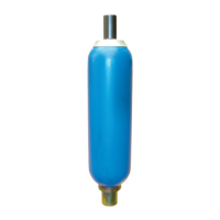
The OLAER IHV series device is a hydropneumatic accumulator, a crucial component in hydraulic systems designed to store and release hydraulic fluid under pressure. Its primary function is to absorb pressure shocks, maintain system pressure, and provide a reserve of fluid for intermittent demands, thereby enhancing the efficiency and longevity of hydraulic machinery. The device operates by compressing a gas (typically nitrogen) in a bladder, which in turn acts on the hydraulic fluid. This design allows for a flexible response to pressure fluctuations, ensuring smoother operation and reducing wear on other system components.
The core function of the IHV series accumulator revolves around its ability to manage hydraulic pressure dynamically. When system pressure increases, hydraulic fluid enters the accumulator, compressing the gas in the bladder. This action stores energy. Conversely, when system pressure drops or additional fluid is required, the compressed gas expands, pushing fluid back into the hydraulic system. This continuous interaction helps to dampen pulsations, compensate for volume changes due to temperature variations, and provide emergency power in case of pump failure. The bladder, made of a flexible elastomer, acts as a barrier between the gas and the hydraulic fluid, preventing their mixing and ensuring the purity of the hydraulic medium. The gas inlet valve allows for precise pre-charging of the bladder with nitrogen, which is critical for the accumulator's optimal performance. The hydraulic valve, located at the fluid end, controls the flow of hydraulic fluid into and out of the accumulator. The design incorporates a robust vessel casing capable of withstanding high pressures, ensuring safety and reliability in demanding industrial environments.
The IHV series accumulator is designed for straightforward integration into various hydraulic systems. Its compact form factor allows for flexible mounting options, although it is recommended to install it horizontally in a vice or other fixation system during maintenance to prevent damage. The device is equipped with a gas inlet valve for pre-charging, which requires a specialized tester and pressurizer instrument (OLAER OSP 746) for accurate inflation and deflation. This ensures that the bladder is charged to the correct pressure, which is vital for the accumulator's efficiency and the overall performance of the hydraulic system. The hydraulic end features a flange or reduction for connection to the hydraulic circuit, allowing for easy installation and removal. A venting screw is also provided to facilitate the release of air during initial system setup, ensuring a fully hydraulic circuit. The nameplate, which is secured by a sub-assembly nut, contains important device information and should be handled carefully during maintenance. The robust construction and internal components are designed for durability, making the IHV series suitable for continuous operation in industrial settings.
Maintenance of the IHV series accumulator is critical for its longevity and safe operation, and the manual provides detailed instructions for dismantling, cleaning, inspection, and reassembly.
The process begins with safety precautions: disconnecting and closing the accumulator inlet, and discharging hydraulic fluid. The accumulator should then be removed from its mounting and secured horizontally. The lead seal and protective cap(s) of the gas inlet valve are removed, followed by deflating the bladder using the OLAER tester and pressurizer instrument (Fig. 1). The gas inlet valve is unscrewed (Fig. 2), and the nameplate is released by removing its sub-assembly nut (Fig. 3). The flange or reduction from the hydraulic fluid end is unscrewed. The venting screw is dismantled carefully, ensuring the gasket ring is not damaged (Fig. 4). The ring nut and gland ring are released (Fig. 5). The hydraulic valve is then carefully pushed inside the vessel casing (Fig. 6), and the O-ring is extracted. The divided anti-extrusion ring/retention ring is separated from the hydraulic valve sub-assembly, folded together, and removed from the vessel (Fig. 7). Finally, the hydraulic valve is removed, and the bladder is extracted through the hydraulic end opening (Fig. 8).
All metallic parts must be thoroughly cleaned and dried with compressed air. A meticulous inspection of the vessel for internal damage is crucial. The valve head should be depressed to check for correct valve operation. The safety nut on the valve tappet must be checked for full tightening and security with Loctite. The O-ring should be inspected for any signs of wear or rubbing. The bladder must be carefully examined for major frictional wear or other damage; it is explicitly stated that the bladder should never be repaired but replaced if damaged. All worn or damaged parts must be replaced.
Before reassembly, it is essential to ensure no foreign bodies are present in the accumulator. To ease bladder reassembly, both the bladder and the vessel interior should be smeared with system hydraulic fluid. The upper part of the bladder is pressed together and fed through the hydraulic end opening (Fig. 8). The nameplate and gas inlet valve sub-assembly nut are lightly screwed on (Fig. 9). It is critical to verify that the bladder is neither folded nor twisted. The hydraulic valve is then placed into the vessel (Fig. 10). The divided anti-extrusion ring/retention ring is inserted into the vessel and positioned on the hydraulic valve. The hydraulic valve is retracted to sit on the interior of the vessel. The O-ring and gland ring are mounted (Fig. 11), and the ring nut is screwed on, centralizing the parts. The hydraulic valve is carefully struck from all sides with a plastic hammer while tightening the ring nut by hand (Fig. 12). The ring nut is then fully tightened (Fig. 13). Before mounting the reduction on the hydraulic end, the bladder is slowly inflated with nitrogen to a pressure of 1-1.5 bar using the tester and pressurizer instrument. The hydraulic valve seal is checked by manipulating the valve tappet. The venting screw and gasket are mounted (Fig. 14). The nameplate and gas inlet valve sub-assembly nut are fully tightened (Fig. 9). Finally, the accumulator is inflated to the system's required precharge pressure.
Before pressurizing the system, it must be vented via the venting screw. The screw should be carefully retightened as soon as hydraulic fluid exits the vessel. The hydraulic system is then pressurized to its maximum, and all connections and gaskets are checked for seals. It is strictly prohibited to undertake any welding, soldering, or mechanical operations on the accumulator. Hydropneumatic accumulators are subject to official pressure vessel regulations, requiring regular inspections. The specific inspection intervals vary by state, and users are advised to consult local authorities for the applicable requirements.
| Series | IHV |
|---|---|
| Fluid Compatibility | Hydraulic Oil |
| Operating Temperature | -20°C to +80°C |
| Maximum operating pressure | 350 bar |
| Connection type | Threaded |