Do you have a question about the OLIMEX A20-OLINUXINO-LIME2 and is the answer not in the manual?
Provides an overview of the manual's scope and board features.
Lists the key hardware specifications and capabilities of the A20-OLinuXino-LIME2 board.
Describes the intended audience and primary applications for the OLinuXino LIME boards.
Details the different versions of the A20-OLinuXino-LIME2 board based on onboard flash memory.
Specifies the hardware revision of the board used during the manual's creation.
Outlines the structure and content of each chapter within the user's manual.
Guides users through the initial setup process for the development board.
Provides crucial safety instructions regarding electrostatic discharge and electrical polarity to prevent damage.
Lists the necessary and recommended items required for setting up and operating the board.
Explains the different methods for powering the A20-OLinuXino-LIME2 board safely and effectively.
Describes the functions of the PWR, RESET, and RECOVERY buttons on the board.
Details the various methods available for interacting with the A20-OLinuXino-LIME2 board.
Explains how to establish a serial connection using the UARTO connector for debugging and communication.
Covers connecting and using an HDMI monitor for video output from the board.
Discusses connecting and using various LCD displays with the board for visual output.
Details how to use SSH over a mini USB connection for remote access in Debian.
Explains how to establish an SSH connection using the Gigabit Ethernet port for remote access.
Guides users on how to modify the board's video output resolution for different displays.
Provides instructions for connecting and calibrating external displays, including touchscreens.
Details the process of calibrating touch displays specifically for Android operating system.
Explains how to calibrate touch screens when using the Debian Linux operating system.
Describes how to use and manage General Purpose Input/Output (GPIO) pins in the Debian environment.
Covers the usage of I2C and SPI communication protocols within the Debian Linux environment.
Provides information on available software images, updates, and support resources for the board.
Introduces the chapter's content, which details the main components of the board.
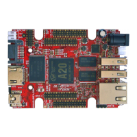
Illustrates and identifies the main components on the top side of the A20-OLinuXino-LIME2 board.
Illustrates and identifies the main components located on the bottom side of the A20-OLinuXino-LIME2 board.
Introduces the chapter focusing on the board's central microcontroller unit.
Details the features and specifications of the Allwinner A20 processor.
Presents a block diagram illustrating the internal architecture and modules of the A20 processor.
Introduces the chapter covering reset circuits, clock sources, and power supply.
Explains the hardware reset mechanism controlled by the power system management IC.
Identifies the locations of the quartz crystals used for system clocks on the board.
Describes the power supply circuit, its components, and input requirements.
Introduces the chapter that details the board's connectors, pinouts, and jumpers.
Details the UARTO interface used for serial communication and debugging.
Describes the microSD card slot and its usage for booting the operating system.
Provides the pinout and schematic details for the SD/MMC1 (microSD) connector.
Details the DC barrel jack connector used for powering the board.
Explains the USB OTG connector's function for firmware updates and tethering.
Details the two USB HOST connectors, their pinouts, and power capabilities.
Describes the Gigabit Ethernet port and its configuration for network connectivity and SSH.
Details the HDMI connector, its pinout, and usage for video output.
Explains the SATA connector for hard drives and its power options.
Introduces the four GPIO connectors and their general usage for peripherals.
Details the pinout and signals for the GPIO-1 connector, including audio and VGA.
Details the pinout and signals for the GPIO-2 connector, used for additional hardware and debugging.
Details the pinout and signals for the GPIO-3 connector.
Details the pinout and signals for the GPIO-4 connector, featuring remaining signals.
Details the LCD_CON connector for connecting LCD displays and its pinout.
Explains the function and default positions of the various SMT jumpers on the board.
Lists and briefly describes additional hardware components not covered in detail elsewhere.
Introduces the chapter dedicated to the board's schematics and design files.
Provides information on accessing and using the Eagle CAD schematics for the board.
Presents the physical dimensions of the board in mils, with a diagram.
Introduces the chapter covering document revisions, board changes, and support information.
Lists the history of document revisions, including changes made and affected pages.
Details the notable changes for different hardware board revisions.
Provides links to relevant web pages, support forums, and purchase codes for the device.
Answers common questions regarding board operation, temperature range, and troubleshooting.
Explains how to modify board configurations and definitions in Debian Linux.
Addresses booting Debian from NAND and provides relevant information.
Provides instructions and links for generating bootable Debian Linux SD card images.
Answers whether mainline kernels can be used instead of the Sunxi kernel.
Addresses the issue of Android not being pre-loaded on the 4GB board version.
Provides contact information and guidelines for product support, returns, and warranty inquiries.
| Brand | OLIMEX |
|---|---|
| Model | A20-OLINUXINO-LIME2 |
| Category | Single board computers |
| Language | English |