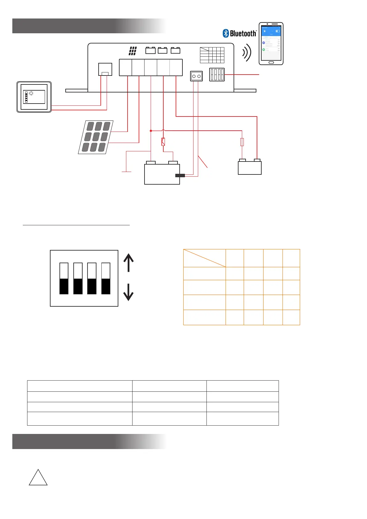
Connection Plan
+
-
-
Ⅰ
+
Ⅱ
Ⅰ
+
main
Ⅱ
START
+
Temp.se nser
Ⅰ
MAIN
Batter y type
Ⅰ
MAIN
1 2 3 4
GEL
Lead Acid
AGM2
LiFePO4
↑
↑↑↑
↑
↑↑↑
↑
↑↑↑
↑↑
↑
↑
Battery 12V
Ⅰ
Main
Ⅱ
START
-
+
+
-
+
-
Select the battery
type of mai battery
(See Battery type table)
Main battery
Temperature
Sensor
(option)
Battery selection
Battery type
1 2 3 4
GEL
Lead Acid
AGM2
LiFePO4
↑
↑↑↑
↑
↑↑↑
↑
↑↑↑
↑↑
↑
↑
Total capacity of panel
MPPT5012A-DUO-BT max.165W
MPPT5025A-DUO-BT max. 350W
NOTE:
Install the solar controller near
the main battery
Vehicle
chassis
main battery
motor battery
(option)
Fuse
5A
Note:
The connection plan shows the maximum terminal assignment for operation of all existing functions of the solar
controller. The minimum terminal assignment consists of the solar panel inputs ("+" and "-") and the connections of
the main battery.
Always connect the fuses as close as possible to the batteries (cable protection!).
Required Cable Cross Sections, MPPT5012A-DUO MPPT5025A-DUO
+/- Panel cables, length as required 2.5-4 mm 2 6-10 mm 2
+/- Battery I cables, length max. 2 m 2.5-4 mm 2 6-10 mm 2
Fuse close to battery I 20 A 40 A
Notes
Connection
*The polarities ( + and - ) of solar panel and batteries are absolutely to be observed!
Observe the cross-sections and length measures of the cables!
!
*Connection of the solar controller to the battery "Board I" should be effected first. Cable
Protection:
the fuses near the batteries into the + cables (protection against cable fire)!
*The solar panels should be protected from direct sunlight (by covering or shading) prior to connection.
13 . 3V
LCD Meter
(option)
1 2
3
4
ON
DIP
Fuse
 Loading...