Do you have a question about the OMB MT-MR PLATINUM and is the answer not in the manual?
Guidelines for proper installation of equipment to ensure functionality and safety.
Responsibility for damages during equipment transportation.
Responsibility for damages during equipment storage.
Responsibility for inadequate use of equipment in projects not performed by specialists.
Important recommendations for connecting OMB equipment to mains power for safe operation.
Standard good practices to follow when maintaining the equipment covered in this manual.
Procedures and techniques for providing emergency assistance in case of electrical shock.
Procedures for treating burns resulting from electrical shock.
Overview of factors determining the reliability of microwave analogic links.
Factors affecting atmospheric attenuation in radio wave propagation.
Method for analyzing terrain profile along propagation path using topographic charts.
Explanation of Fresnel zones and their importance for path clearance in radio links.
Types and specifications of coaxial transmission lines suitable for radio links.
Core calculations for antenna selection and system link budget.
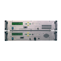
Overview of the MT-MR Platinum Radio Link System as an STL.
Technical specifications for the MT-MR Platinum radio link system.
Guidelines for proper system operation, installation, grounding, and maintenance.
Detailed description of the MT Platinum transmitter's function and design.
Detailed technical specifications for the MT Platinum transmitter.
Function and operation of the audio processor unit for baseband signal handling.
Function of VCO and PLL units in generating and stabilizing RF carrier frequency.
Role of the microcontroller unit in controlling transmitter parameters and interface.
Diagram illustrating the front panel layout and controls of the MT-DIG Platinum transmitter.
Overview of the MR Platinum receiver's functionality and integration in STL systems.
Technical specifications for the MR Platinum receiver.
Detailed performance characteristics and tuning procedures for the receiver.
Diagram illustrating the front panel layout and controls of the MR DIG Platinum receiver.
Procedures for unpacking, checking, and performing back-to-back tests of transmitter and receiver.
Guidelines for operating and maintaining the MT-MR Platinum system, including blower replacement.
Block diagram showing the functional interconnections of the MT Platinum transmitter modules.
Detailed schematic diagram of the MT Platinum transmitter's main board circuitry.
Diagram illustrating the front panel layout and controls of the MT Platinum transmitter.
Schematic of the MT Platinum transmitter's main circuit board.
Polarization voltage and current measurements for the PD55003 driver.
Polarization voltage and current measurements for the PD55025 final stage.