5
MANUTENZIONE
E REGOLAZIONI
MAINTENANCE
AND ADJUSTMENT
26
OMCA S.r.l - Via Curiel, 6 - 42025 - Cavriago (RE) - ITALY
Telefono: +39 0522 943502 / +39 0522 943503 - Website: www.omcasrl.it - E-mail: info@omcasrl.it
5.1
5.1 SOSTITUZIONE INSERTI 5.1 INSERTS REPLACING
ATTENTION:
MAKE THIS OPERATION WITH CARE BECAUSE THE INSERTS
ARE SHARP.
ATTENZIONE:
QUESTA OPERAZIONE DEVE ESSERE SVOLTA CON ATTENZIONE
IN QUANTO GLI INSERTI SONO TAGLIENTI.
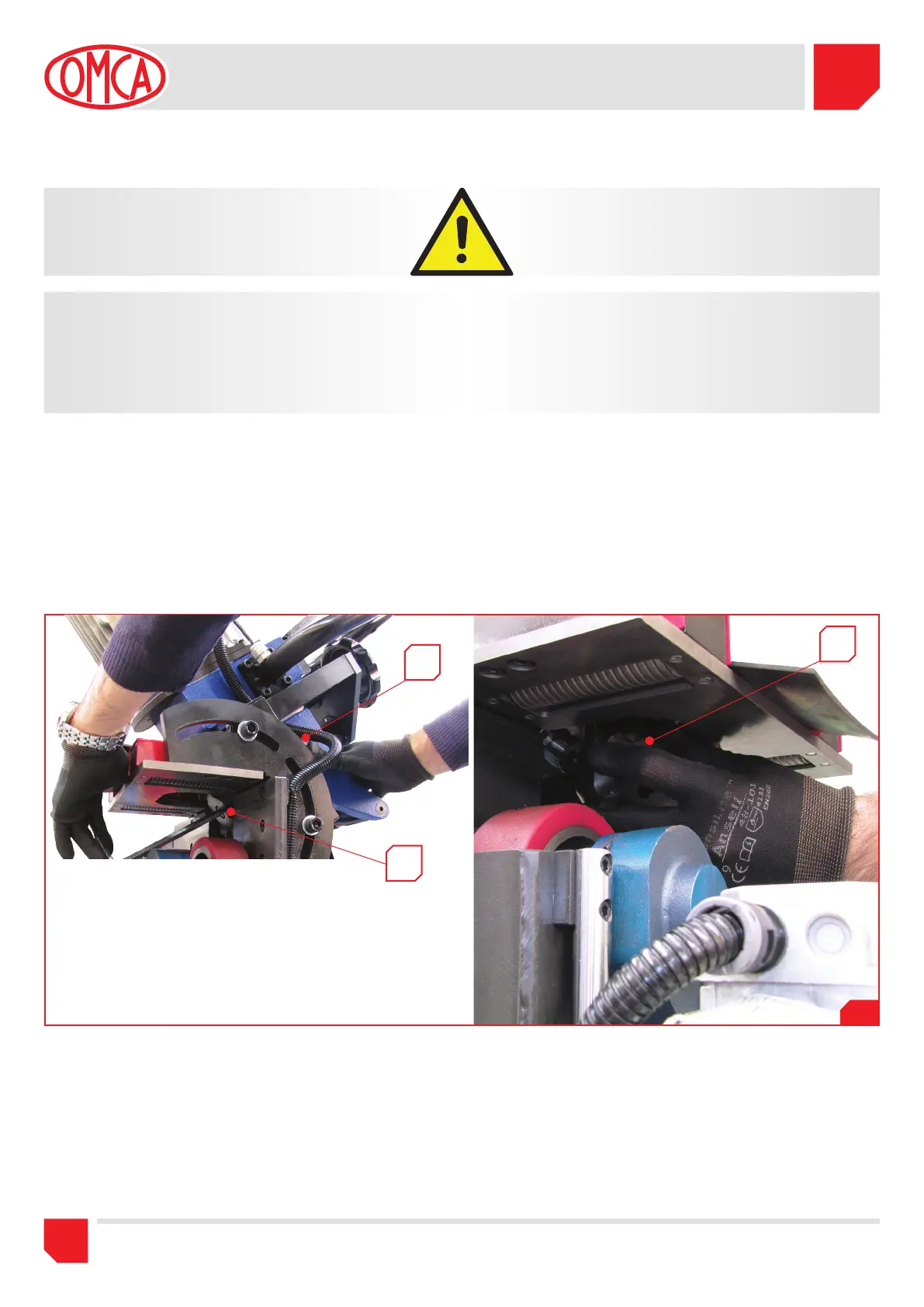
1) Prima di effettuare questa operazione, accertarsi che la macchina
sia spenta (interruttore su OFF (O)).
2) Premere il pulsante (Fig.5.1 pos.A) che blocca la rotazione del
mandrino, nel mentre allentare la vite (Fig.5.1 pos.B) che fissa la
fresa al mandrino.
3) Rilasciare il pulsante (Fig.5.1 pos.A) e svitare completamente la
vite, rimuovere la fresa dalla propria sede (Fig.5.1 pos.C).
1)
Before carrying out this operation make sure that the machine is
switched off (switch on OFF (O) position).
2) Push the button (Pic.5.1 pos.A) that lock the spindle rotation, in
the meanwhile loosen the screws that fix the cutter to the spindle
(Pic.5.1 pos.B).
3) Release the button (Pic.5.1 pos.A) and unscrew completely the
screw and remove the cutter from its seat. (Pic.5.1 pos.C)
L’OPERATORE RAPPRESENTATO NELLA FOTO SOTTOSTANTE NON
È MUNITO DI PROTEZIONI ANTINFORTUNISTICHE, QUESTO È STATO
NECESSARIO PER FARE COMPRENDERE NEL MIGLIORE DEI MODI
L’OPERAZIONE DA COMPIERE.
PERTANTO SI RICORDA DI UTILIZZARE SEMPRE LE PROTEZIONI
ANTINFORTUNISTICHE.
THE OPERATOR SHOWED IN BELOW PICTURE DOES NOT WEAR WITH
THE SAFETY PROTECTION, THIS HAS BEEN NECESSARY TO LET YOU
UNDERSTAND IN THE BEST WAY POSSIBLE WHICH IS THE OPERATION
YOU HAVE TO EFFECT.
FOR THIS REASON WE REMIND YOU TO USE ALWAYS THE SAFETY
PROTECTION.
4) A questo punto (come indicato in Fig.5.2) la fresa è completamente
accessibile: quindi allentare i grani di bloccaggio degli inserti
(Fig.5.2 pos.A), pulire accuratamente la loro sede e ruotare gli
stessi per utilizzare il lato nuovo tagliente. Al termine stringere il
grano che fissa l’inserto.
Sostituire gli inserti quando sono stati utilizzati tutti i lati taglienti e si
rileva un potere di taglio ridotto.
A
C
B
4) At this point (as showed in Pic.5.2) the cutter is completely
accessible, loosen the inserts (Pic.5.2 pos.A), clean carefully
their seats turn them and use the new sharp side. At the end,
tighten the screw to the inserts.
Replace the inserts when all the sharpen sides have been used and it
is noticed a lower cut power.
 Loading...