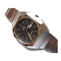
1973
Cal. 1310
8
EXCHANGE OF ELECTRONIC MODULE
3.17. Open the case.
3.18. Remove upper magnetic protection No.
1310.9230 by turning the watch over.
3.19. Remove power cell bridle and power cell
(point 1, fig. 1.3.)
3.20. Unscrew the 2 motor connecting screws No.
2377 (2), earth screw No. 2589 (3), electronic
module screw No. 2589 (4) and electronic
module screw No. 2377 (5).
3.21. Extract faulty electronic module No.
1310.9100.
3.22. Place new electronic module in position.
Important : For this operation, the hand-setting
stem must be pushed in.
3.23. Tighten the 5 screws according to op. 3.20
and fig. 1.3.
3.24. Follow operations in the order 3.12 to 3.16.
EXCHANGE OF MOTOR MODULE
3.25. Follow operations in the order 3.1 to 3.5.
3.26. Release retaining click No. 1310.9028
(point 6, fig. 2.3.) by slightly turning the click
stud (6a).
3.27. Remove the second hand.
3.28. Unscrew the wheel train bridge screw No.
2377 (7) and withdraw the wheel train bridge No.
1310.9001.
3.29. Remove second wheel No. 1310.9010 and
third wheel No. 1310.9014.
Fig. 1.3
Fig. 2.3

 Loading...