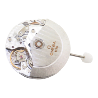
1973
Cal. 1310
9
3.30.
Unscrew the 2 motor connecting screws (2),
motor module screw No. 2377 (8)
and motor eccentric locking screw No. 2582
(9).
3.31.
Extract faulty motor module No. 1310.9200.
3.32.
Place new motor module in position.
3.33.
Important : Screw very slightly the 2 motor
connecting screws (2) and motor module
screw (8).
3.34.
Fit simultaneously the third and second
wheels.
3.35.
Fit wheel train bridge and tighten its screw.
3.36.
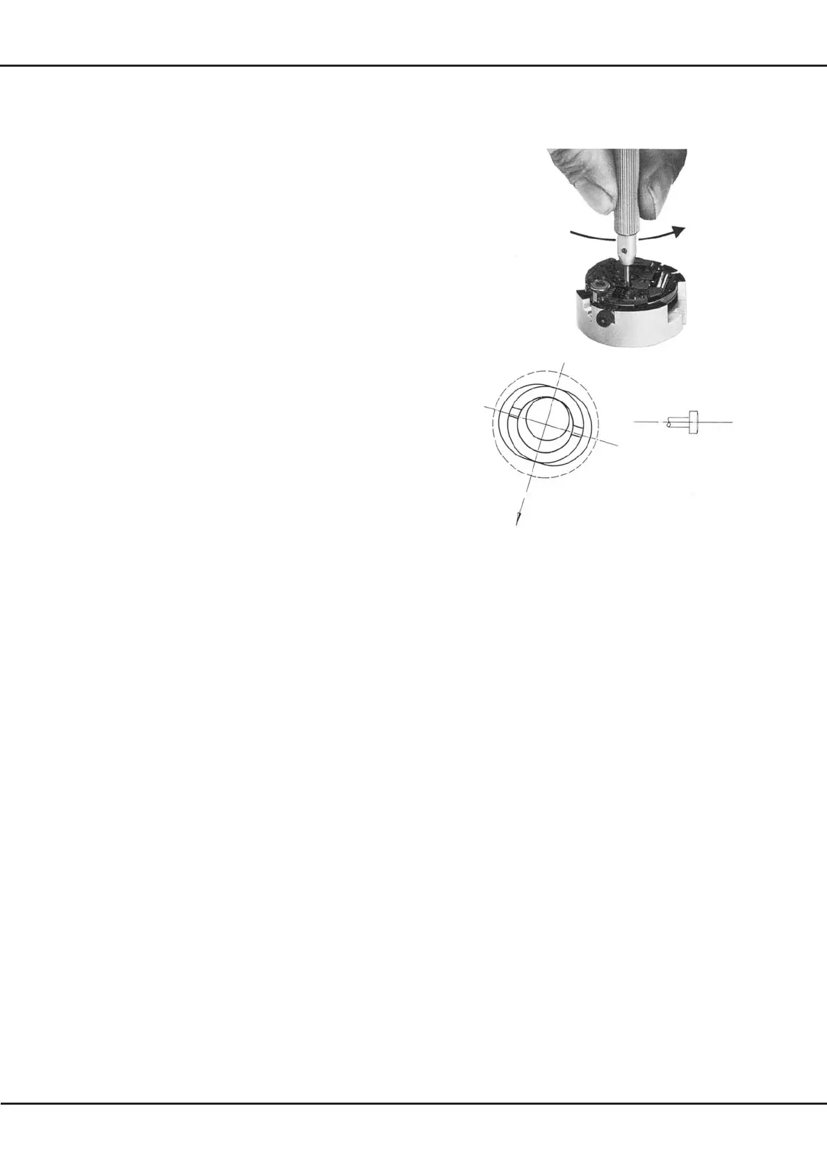
Adjustment of motor-second wheel backlash
by motor eccentric No. 1310.9227. Turn
motor eccentric clockwise until wheel train is
stopped, using the tool specially devised for
this purpose (fig. 3.3.). If locking of the motor
is impossible, the eccentric should be left in
its position of maximum eccentricity (fig. 3.3
(B). The following operation 3.37 will not be
necessary.
3.37.
Turn eccentric slowly in the opposite
direction until the wheel train
turns normally, i.e. always in the same
direction (the wheel train is free, without
backlash).
Important : Check rotation of wheel train
curing one minute at least.
3.38.
The backlash between motor and second
wheel is then obtained by turning the motor
eccentric through an angle of 40°. To secure
this angle accurately, place tool on eccentric,
hold with one hand the upper part of the
instrument, and with the other hand turn
handle arrow-wise (fig. 3.3.) as far as tool
banking.
For the movements which have not been
stopped by operation 3.36, check that the
wheeltrain is always turning in the same
direction, then effect the 40° recoil.
Fig. 3.3
wheel-train bridge direction
Fig. 3.3. (B)
Important : If a faulty operation has occurred
in adjusting the backlash, it will be necessary
to recommence the entire adjustment as from
operation 3.36, and to follow the indications
scrupulously.
3.39.
Tighten the motor eccentric locking-screw.
3.40.
Lock motor module screw and the 2 motor
connecting screws.
3.41.
Adjustment of click by microscope : This
operation is carried out in "stop second"
position of the hand setting stem. Before
adjustment, turn the hand setting stem arrow-
wise in order to compensate the backlash.
 Loading...