This document provides installation and operating instructions for Omega Gas Hobs, covering models OG30XA, OG60XA, OG60WA, OG61XA, OG61WA, OG62XA, OG63XA, OG64XA, OG65XA, OG66XA, OG67XA, OG70XA, OG71XA, OG72XA, OG90XA, OG91XA, OG92XA, OGG64A, OGG75A, and OGG96A.
Function Description
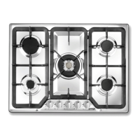
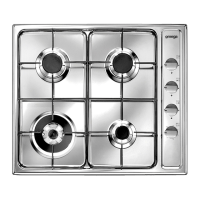
The Omega Gas Hob is a domestic cooking appliance designed for cooking and heating up food. It is intended for use by adults only and should not be used as a space heater. The appliance features multiple burners for various cooking needs.
Important Technical Specifications
The hob is suitable for installation with Natural Gas (NG) or Universal LPG (ULPG).
- Gas Type: Natural Gas or ULPG.
- Pressure Regulator (NG): A pressure regulator is supplied and MUST be fitted to the ½” thread on the elbow at the rear of the hot plate for Natural Gas installations. The NG regulator MUST be checked and adjusted to 1.0 kPa after installation.
- Pressure (ULPG): For ULPG, the appliance can be connected directly to the inlet fitting. The pressure MUST be checked to ensure the supply is operating at 2.75 kPa. A separate test point fitting must be installed between the piping and the appliance for pressure checking.
- Gas Connection: Connection to the gas supply must comply with AS 5601. A ½” BSP connector at the inlet is recommended. The gas supply line should be of adequate length for service/disconnection and can be annealed copper pipe or a hose assembly complying with AS1869, Class 'B', 10mm diameter, maximum length 1000mm.
- Electrical Connection: The appliance requires a 240 Volt, 50 Hz, single phase outlet and comes with a 3-pin plug. All appliances MUST be earthed. Electrical wiring must comply with local electrical authority regulations and be carried out by a qualified electrician.
- Burner Injector Sizes and Nominal Gas Consumption:
- Natural Gas (1.00 kPa):
- Small Burner: Injector size 0.90 mm, 3.6 MJ/h
- Medium Burner: Injector size 1.15 mm, 6.3 MJ/h
- Large Burner: Injector size 1.55 mm, 10.8 MJ/h
- Wok Burner: Injector size 1.75 mm, 13.2 MJ/h
- Fish Burner: Injector size 1.55 mm, 10.8 MJ/h
- ULPG (2.75 kPa):
- Small Burner: Injector size 0.55 mm, 4.0 MJ/h
- Medium Burner: Injector size 0.66 mm, 6.3 MJ/h
- Large Burner: Injector size 0.85 mm, 10.2 MJ/h
- Wok Burner: Injector size 0.98 mm, 12.6 MJ/h
- Fish Burner: Injector size 0.85 mm, 10.2 MJ/h
- Clearances (from AS5601):
- Above Cookers (Measurement A): Range hoods and exhaust fans must be installed according to manufacturer instructions. Clearance between the highest part of the hob and a range hood must be no less than 600mm, or 650mm for an overhead exhaust fan. Any other downward facing combustible surface less than 600mm above the highest part of the hob must be protected for the full width and depth of the cooking surface area, with a minimum clearance of 450mm.
- Side Clearances (Measurements B & C): If the distance (B) from the periphery of the nearest burner to any vertical combustible surface is less than 200mm, the surface must be protected to a height (C) of not less than 150mm above the hob for the full dimension of the cooking surface area. If the appliance has a 'splashback', rear wall protection is not required.
- Freestanding/Elevated Appliances (Measurements D & E): If the distance (D) from the periphery of the nearest burner to a horizontal combustible surface is less than 200mm, then E must be 10mm or more, or the horizontal surface must be above the trivet.
- Dimensions (Overall, Gas, and Electrical Connection Points):
- 60cm Hob: A-30mm, B-70mm, C-30mm, D-55mm, E-580mm, F-510mm
- 70cm Hob: A-30mm, B-25mm, C-35mm, D-50mm, E-720mm, F-522mm
- 90cm Hob: A-30mm, B-310mm, C-40mm, D-50mm, E-860mm, F-510mm
- Cut-out Size for Bench Tops: Refer to Figure 5 in the manual for specific dimensions.
- Identification Plate: Located under the casing, it contains technical data, serial number, and markings, including Model Number, AGA or SAI-GLOBAL Approval Number, Gas operating pressure, and Nominal Gas Consumption. This plate MUST NOT be removed.
Usage Features
- Intended Use: The appliance is built for cooking and heating-up of food. Any other uses are considered improper.
- Safety:
- Always ensure control knobs are in the "ZERO" (OFF) position after use.
- Do not put pans with uneven bottoms on the grids.
- Do not use kitchenware or griddle plates that extend beyond the hob's perimeter.
- Do not let unsupervised children play with the hob.
- Do not spray aerosols near the appliance while in operation.
- Gas Type Conversion: The cooktop is manufactured for a specific gas type (marked on the hob/carton). Conversion to another gas type (NG to ULPG or vice versa) may be necessary and MUST be carried out by an Authorized Person. This involves replacing injectors (using a 7mm tube spanner), fitting/removing the regulator, and adjusting the low flame.
- Low Flame Adjustment: After conversion, ignite the burners. Remove the knobs to access the by-pass screw on the gas valve. Use a 2mm screwdriver to adjust the by-pass screw until the burner flame is at its minimum, ensuring it has a length of at least 4mm and does not extinguish when transitioning from maximum to minimum position.
Maintenance Features
- General Care: This manual is an integral part of the appliance and MUST be kept for the entire working life of the cooking hob to maintain its appearance and functional qualities.
- Cleaning:
- Before cleaning, ensure all control knobs are in the "OFF" position and the appliance has cooled completely.
- Before any maintenance, disconnect the appliance from the electricity supply.
- Only use cleaning materials recommended by the manufacturer and suitable for the hob's surfaces.
- DO NOT use caustic pastes, creams, sprays, ammonia cleaners, abrasive cleaning powders or pastes, coarse wire wool/scourers, or any hard implements, as they will damage the surfaces.
- DO NOT use a Steam Cleaner.
- DO NOT use ammonia-based cleaners.
- Always keep the hob dry.
- Servicing: The appliance must be installed with provision to allow the gas to be turned off and disconnected for servicing and removal. If the appliance does not function after installation, disconnect it and call a technical assistance centre. NEVER ATTEMPT TO REPAIR THE APPLIANCE yourself.
- Installation Inspection: Immediately after installation, a brief inspection of the cooking hob should be carried out. The installation connections must be leak tested, and the burner operating pressure and flame checked and adjusted. Warranty service calls do not cover these adjustments.
- Waste Disposal: Do not leave packing materials in the home environment. Separate waste materials and take them to the nearest special garbage collection centre. Replaced appliances MUST be taken to a special garbage collection centre.