Do you have a question about the omisa HST 300 Smart and is the answer not in the manual?
Ensuring proper connection terminal use and contact for safe welding operations.
Guidelines on correct handling of cables to prevent damage and hazards during operation.
Procedures for securely fixing fittings and joints before commencing the welding process.
Instructions for cleaning the welding unit, emphasizing not to spray or immerse in water.
Warning about opening the unit, restricted to qualified personnel for safety.
Specifications and safety advice for using extension cables to ensure proper operation.
Pre-use inspection of safety features and parts for proper function and integrity.
Details on mains and generator power supply requirements, including protection and capacity.
Step-by-step guide for powering on the welding unit and initial display sequence.
Procedure for entering the welder identification code, including manual or scanner input methods.
Instructions for connecting welding terminals to the fitting, ensuring clean and proper contact.
How to use a handheld scanner to read fitting bar codes for automatic parameter input.
Initiating the welding process after data input, including confirmation prompts.
Monitoring and execution of the welding process, displaying real-time parameters.
Successful completion criteria for the welding process, indicated by time correspondence and buzzer.
Identifying and acknowledging errors that cause the welding process to fail.
Adhering to manufacturer-specified cooling times for the joint after welding.
Resetting the unit to the parameter input stage after welding is completed.
Utilizing the ViewWeld feature for reviewing welding reports and printing labels.
Inputting traceability data such as welder ID and commission number for reports.
Procedure for entering or modifying the commission (job) number for welding reports.
Guide to manually inputting voltage and time parameters for welding.
Process for manually entering fitting codes or parameter strings using the keypad.
Choosing the output format for downloaded welding reports (PDF, DataWork, CSV).
Procedure for downloading all saved welding reports in the selected file format.
Methods to download specific reports based on commission, date, or report number ranges.
Information on the download process, including completion messages and error handling.
Steps for securely deleting welding report data from the unit's memory.
Guidance on preserving report data in memory for future printing or retrieval.
Accessing technical information like software version and maintenance dates.
How the unit measures fitting resistance and identifies errors based on tolerance.
Explanation of the overheating protection mechanism that halts the welding process.
Interpreting the 'Power Supply Failure' message and how to proceed.
Details on settings like code expiry, memory control, and manual input options.
How to choose the preferred language for the unit's display and reports.
Procedure for setting the current date and time on the welding unit.
Option to select between Celsius and Fahrenheit for temperature readings.
Configuration of data recording for welder code, commission number, and traceability.
Common errors encountered during data entry, such as code errors or system faults.
An erroneous input has occurred, a code tag is poor or has an error in code symbology.
Indicates no electrical contact between the unit and fitting, or a defective heater coil.
Input voltage is below the operational threshold, requiring adjustment of generator output.
Input voltage exceeds the operational threshold, requiring generator output adjustment.
Transformer temperature is too high; unit requires cooling down.
Critical system error detected during auto-test; unit requires professional repair.
Measured ambient temperature is outside the unit's operating range.
The ambient temperature sensor on the welding cable is damaged or defective.
Internal system clock is malfunctioning; requires reset or service.
The recommended service date is overdue; unit requires servicing.
Incorrect code entered or missing welding time during manual input.
System memory is full of reports; requires printing or downloading.
An error occurred during data transfer or printing that could not be cleared.
Errors occurring while welding is in progress, indicated by audible alarms.
Input voltage is below 175 volts; process aborts if condition persists.
Input voltage is over 290 volts; process aborts if condition persists.
Fitted resistance value is outside the read tolerance, aborting the process.
Input voltage frequency is out of the specified tolerance range (42 Hz - 69 Hz).
Output voltage does not correspond to the previously read value; unit needs service.
Momentary current failure or significant decrease in current.
Output current value is in excess, potentially due to short-circuit.
Welding process interrupted by pressing the STOP/RESET key.
Dynamic current differs from required value, indicating heater coil short-circuit.
Last welding incomplete due to power supply disconnection; requires acknowledgment.
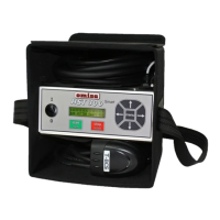
| Brand | omisa |
|---|---|
| Model | HST 300 Smart |
| Category | Soldering Gun |
| Language | English |