Do you have a question about the Omnitracs SR4 Kenworth T680 and is the answer not in the manual?
Details the different SR4 harness SKUs and cable types for Kenworth T680/T880.
Preferred and alternative mounting locations for cameras, sensor bars, and keypads on flat windshields.
Preferred and alternative mounting locations for cameras, sensor bars, and keypads on split windshields.
Specifies primary locations for the controller and ECU port within the vehicle cabin.
Identifies driver-side locations for constant power, true ignition, and ground wiring.
Lists available spare battery locations within the vehicle's upfitter block for power connections.
Details how to connect constant power, true ignition, and ground using upfitter plugs or add-a-fuses.
Provides a diagram of the fuse box with labels for each fuse and relay slot.
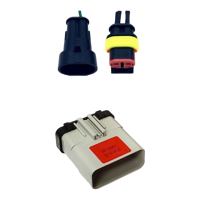
Describes the 2-Pin TE connector, its part number, network, and baud rate for data link connection.
Specifies primary locations for the controller and ECU port within the vehicle cabin for 2018-2023 models.
Identifies passenger-side locations for constant power, true ignition, and ground wiring.
Lists available spare battery locations within the vehicle's upfitter block for power connections.
Details how to connect constant power, true ignition, and ground using upfitter plugs or add-a-fuses.
Provides a diagram of the fuse box with labels for each fuse and relay slot for 2018-2023 models.
Describes the 14-pin PACCAR connector, its part number, network, and baud rate for data link connection.
Lists specific VSAs that describe the installation process for 360 Convoy cameras.
Mount the ADAS shroud 1" from the top center of the windshield, avoiding driver's line of sight.
Steps for cleaning, mounting, and running cables for the ADAS forward-facing camera.
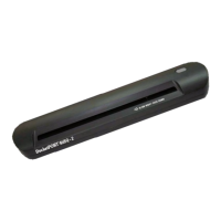
Mount the device on the right-hand side of the steering wheel, near the top of the dash.
Steps for cleaning, securing, and running wires for the driver feedback device.
Recommendations for adjusting camera mounts when sun visors or third-party devices cause obstructions.
Detailed steps for mounting and securing the forward-facing camera, ensuring proper field of view.
Detailed steps for mounting and securing the cab-facing camera, ensuring driver visibility.
Instructions on mounting the cab-facing camera to avoid blocking infrared sensors and causing flare.
Steps to adjust the forward-facing camera angle using a security wrench for optimal view.
Visual guide showing acceptable fields of view for the forward-facing camera.
Visual guide showing acceptable fields of view for the cab-facing camera.
Instructions for mounting the sensor bar, ensuring visibility and avoiding airbag interference.
Instructions for mounting the keypad bracket and securing the keypad unit.
Best practices for managing and securing cables, including service loops, zip ties, and connector checks.
Details approved connection methods using heat shrinkable and water-resistant connectors.
Lists prohibited connection methods like Scotchloks and T-Taps due to reliability concerns.
How to test and verify uninterrupted constant power using a digital multi-meter.
How to test and verify true ignition power using a digital multi-meter.
How to locate and connect the chassis ground wire securely.
Warning against connecting to negative ground MPC/LVD; system requires positive connections.
Instructions for connecting to the positive post of the vehicle battery or MPC/LVD switch.
Identifies and describes the function of various controller connection ports like Expansion, ECU/PWR, and Analog.
Instructions for connecting forward/cab-facing cameras, cellular, and WIFI antennas to the controller.
Instructions for connecting analog cameras (e.g., 360 cameras) to the controller's analog ports.
Explains the Power LED indicators for external power status.
Explains the Ignition LED indicators for ignition status.
Explains the System LED indicators for system operation and battery status.
Steps to prepare the vehicle and system for diagnostic mode and check cellular connectivity.
How to start Diagnostic Mode by pressing the green button on the keypad or feedback device.
How to interpret and address fault codes displayed during Diagnostic Mode.
Guide on using the SmartDrive Technician App to perform self-checks for installation quality assurance.
Overview of the VSA as the approved hardware and wiring specification for the vehicle.
Guidelines for contacting managers and documenting any deviations from the VSA.
A section to document any approved exceptions to the installation specification.
| Brand | Omnitracs |
|---|---|
| Model | SR4 Kenworth T680 |
| Category | Automobile Accessories |
| Language | English |