61F-G@
11
Liquid Level Indication and Alarm
Basic Type
61F-I
Dimensions:
page 13
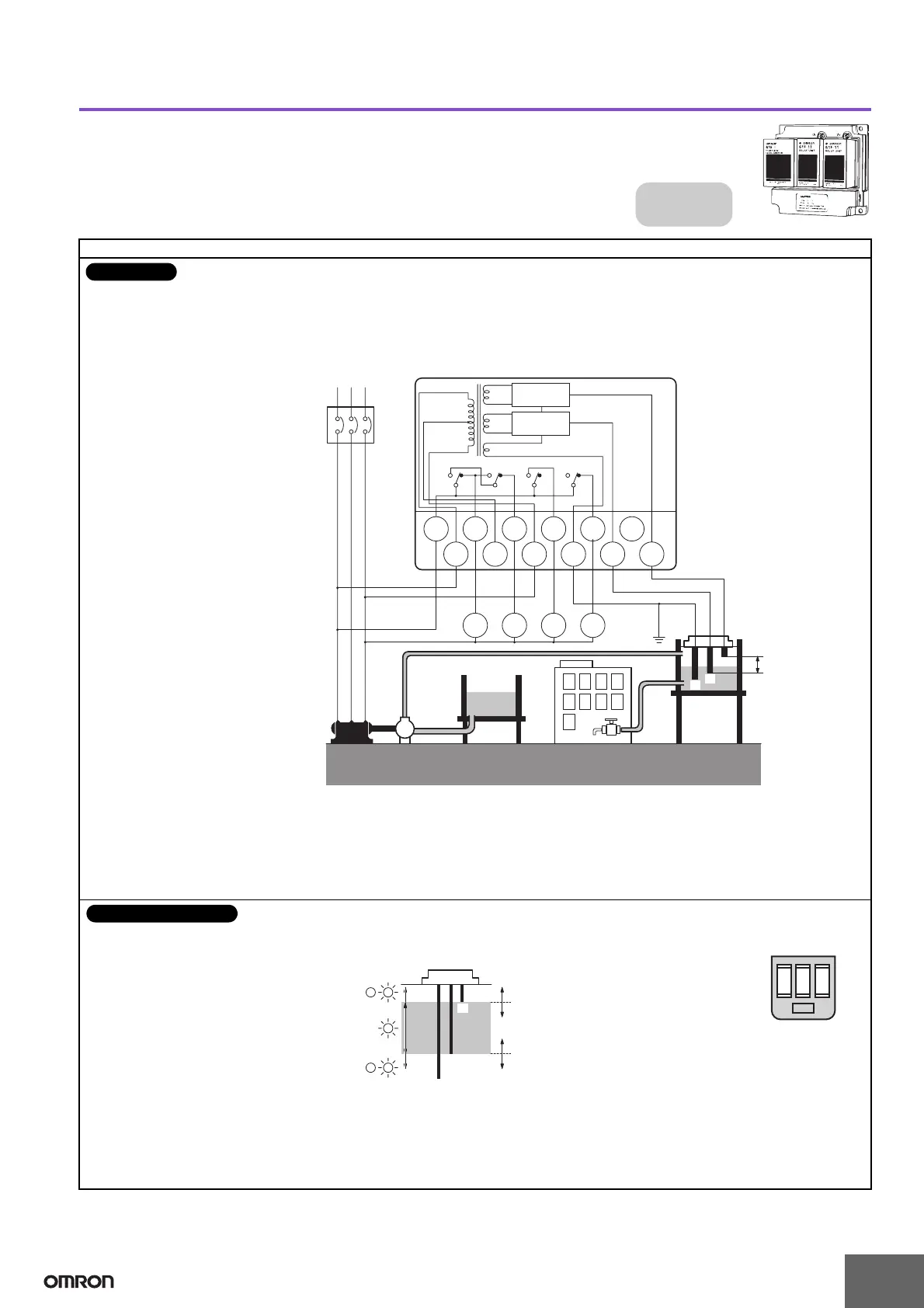
Liquid Level Indication and Alarm
Water supply
source
MCCB
RS
MP
T
220-VAC power supply 61F-I
Water
tank
Upper limit Lower limit
Intermediate
Alarm
Upper alarm
PS-3S
Lower alarm
Intermediate
(See note.)
E
1
S0 S1 S2 E3 E2 E1
TC BL3 L2
BPLPL
L
1
PL
61F-11
Relay Unit
8 V
220 V
110 V
0 V
24 V
24 V
U
1
U2
U2U1U1U2
61F-11
Relay Unit
E2
E3
• Power Supply Connections
110 VAC: Connect S
0
and S
1
.
220 VAC: Connect S
0
and S
2
.
Note: Be sure to ground the common Electrode (the longest Electrode).
Connections
B
LL
E2
E3
Water tank
Lower
limit
Middle
Upper
limit
(U
1 indicator ON)
(U
1 indicator OFF)
(U
2 indicator ON)
(U
2 indicator OFF)
B
LH
LM
E1
U
1
U
2
Power
supply
Relay Unit Location
• When the water level drops below
E
2
, the lower-limit indicator turns
ON and the alarm sounds (U
2
indicator OFF).
• When the water level reaches E
2
,
the alarm turns OFF and the
intermediate indicator turns ON
(U
2
indicator ON).
• When the water level rises to E
1
,
the upper-limit indicator turns ON
and the alarm sounds (U
1
indicator ON).
Principles of Operation

 Loading...