Appendix BSpecifications
196
Type Models Words
allocated per
Unit
Allocation order Example: For I/O
number 0
32 input points C200H-B7A12
2
2 words for inputs 030: input
32 output points C200H-B7A02 2 words for outputs 030: output
16 output points/16 input
points
C200H-B7A21 1 word for outputs →
1 word for inputs
030: output
031: input
32 output points/32 input
points
C200H-B7A22 4 2 words for outputs →
2 words for inputs
030: output
031: output
032: input
033: input
Note B7A Link Terminals with 10-points and B7A Link Terminals with mixed I/O (8 inputs/8 outputs) cannot be
connected to B7A Interface Units. Use 16-point B7A Link Terminals. 16-point B7A Link Terminals include
16-point models (input and output), models with 2 circuits configured with 16 points, and models with 16
points of mixed I/O.
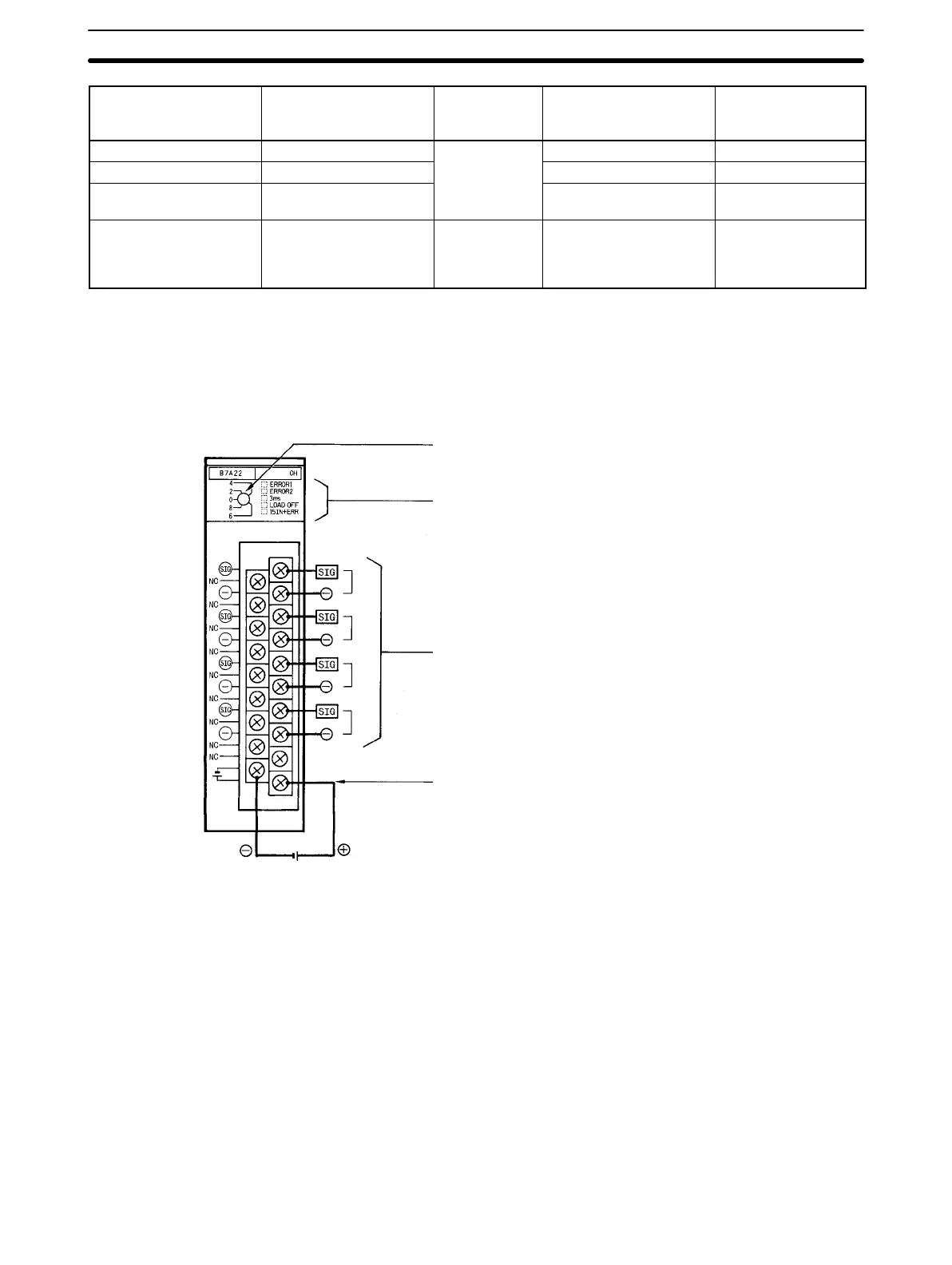
Parts and Names (C200H-B7A22 shown below)
12 to 24 VDC
External Power Supply Terminals
Supply 12 to 24 VDC.
Connection terminals
Connect to the SIG terminal of the B7A Link Terminal
and to the negative power terminal of the B7A Link
Terminal. The actual use of these terminals depends
on the B7A Interface Unit.
12 to 24 VDC
Front
Status indicators
The indicators depend on the model of B7A Inter-
face Unit.
I/O number switch
This switch determines the words allocated to the
Unit.