49
Creating Routing Tables Section 3-8
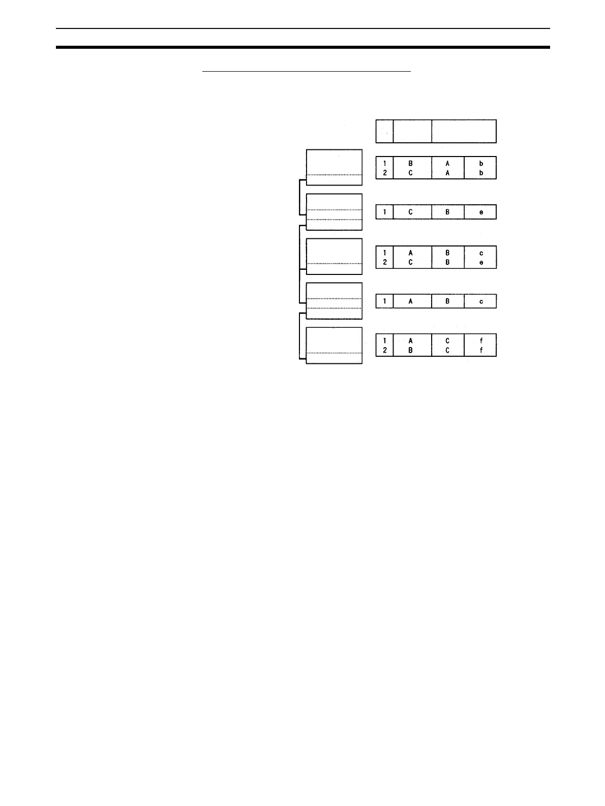
Example 2: Three Interconnected Networks
This example shows the relay network table settings for three different inter-
connected networks.
In the table for PC #3, for example, if network #A is taken as the end network,
then network #B becomes the relay network and node #c becomes the relay
node. If network #C is taken as the end network, then network #B still
becomes the relay network and node #e becomes the relay node.
Relay Network Table
No.
End
network
Relay
network
Node
PC #1
Node #a
Network #A
PC #2
Node #b
Node #c
Node #d
PC #3
Network #B
Network #C
Node #e
PC #4
Node #f
Node #g

 Loading...


