EasyManua.ls Logo

Omron KM-N3-FLK - User Manual

Omron KM-N3-FLK
106 pages
Print Icon
To Next Page IconTo Next Page
Loading...
On-Panel Power Monitor
model KM-N3-FLK
Users Manual
1. Overview of the unit
2. Installation and wiring
3. Basic use
4. Settings needed to measure
electricity
5. Other Functions
6.
Detailed settings for communications
7. Troubleshooting
8. Appendices
Catalog no. N214-E1-02
Thank you for purchasing the On-panel Power Monitor, model KM-N3-
FLK (referred to as model KM-N3 in this manual).
This Users Manual describes the functions, performance, and
application methods needed for optimum use of the unit.
Please observe the following when using this unit.
This product is designed for use by qualified personnel with a
knowledge of electrical systems.
Before using the product, thoroughly read and understand this Users
Manual to ensure correct use.
Keep this Users Manual in a safe location so that it is available for
reference whenever required.

Questions and Answers

  • S
    Sabrina JoyceJul 31, 2025
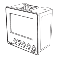
    Why is there a large discrepancy in measured values on my Omron KM-N3-FLK Microphone?
    • B
      bclarkJul 31, 2025
      A large discrepancy in measured values may occur due to several reasons. First, ensure correct wiring. Second, verify and set the correct secondary and primary current values of the CT you are using. If you're using multi-circuit metering, ensure these values are set for all circuits. Also, check that the CTs have appropriate rated current values for the circuit being measured. Finally, confirm that the phase and wire type settings for the measuring circuits are correct.
  • F
    Frank MurphyAug 4, 2025
    What to do if voltage and current can be measured, but power cannot be measured on Omron Microphone?
    • G
      Garrett RodriguezAug 4, 2025
      If your Omron Microphone measures voltage and current but not power, it could be due to a few reasons. If negative electricity is measured, all fitted CTs might be fitted back to front. If the measured electricity is near 0, one of the fitted CTs might be fitted back to front. Also, power cannot be correctly measured if the phase of the voltage is not correct. If the function for warning about miss-wiring is on, correct wiring if "A-VR", "A-VS","A-VT" and "A-W2" are displayed. Finally, if you have selected 1P2W2 or 1P3W2 as the phase and wire type, set the correct voltage allocation for the branching 1-phase 2-wire.
  • M
    matthew71Aug 9, 2025
    Why is RS-485 communications not possible with my Omron Microphone?
    • C
      Courtney Garcia PhDAug 9, 2025
      If RS-485 communication isn't working, first ensure correct wiring. Then, check that the communication settings between your Omron Microphone and the host system match. Also, note that the maximum number of connectable units is 99 for Modbus and 31 for CompoWay/F protocol. When using multi-circuit metering, ensure communication addresses are not duplicated across circuits.
  • K
    Kaitlin SotoAug 13, 2025
    What to do if I cannot measure current with my Omron KM-N3-FLK?
    • L
      Laura CardenasAug 13, 2025
      If you cannot measure current, ensure the CT is connected to the main unit and hasn't separated from the electric wire. Also, ensure that the connection is properly wired according to the connection diagrams.
  • E
    emily49Aug 17, 2025
    What to do if the Omron KM-N3-FLK Microphone main unit doesn't start?
    • L
      Laura HarrisAug 17, 2025
      If the main unit of your Omron Microphone doesn't start, check that the voltage terminals are wired and that the voltage supplied is within the rated range. Also, the unit might be in power saving mode; press any switch to light the LCD again.
  • A
    Amanda JensenAug 22, 2025
    What to do if I cannot measure voltage with my Omron KM-N3-FLK?
    • D
      David HigginsAug 22, 2025
      If you cannot measure voltage with your Omron Microphone, check that the voltage connection matches the phase and wire type you have selected. If you have selected 1P2W2 or 1P3W2 as the phase and wire type, set the correct voltage allocation for the branching 1-phase 2-wire.
  • I
    ihaleyAug 26, 2025
    Why is the pulse not outputting from my Omron KM-N3-FLK Microphone?
    • N
      Nicole FreemanAug 26, 2025
      If the pulse is not outputting, ensure correct wiring. Also, you need to set which of the OUT1/ OUT2/OUT3/OUT4 pulse output terminals to output from, as the default is OFF. Finally, try reducing the pulse output units.

Summary

Agreement regarding use

1. Definitions

Defines key terms used in the agreement, such as Omron products and usage conditions.

2. Cautions regarding content

Points to be aware of regarding catalog content, warranties, and discontinuation.

3. Precautions

Terms deemed accepted upon adopting or using Omron products, including safety and application fitness.

Agreement regarding use(continued)

3. Precautions (continued)

Details on applications with stringent safety requirements and high reliability.

4. Warranty

Explains warranty period, content, exceptions, and limitation of liability.

5. Limitation of liability

States the warranty is entire and Omron accepts no responsibility for damages.

6. Export control

Requires compliance with export control laws for Japan and related nations.

Notice

Permissions regarding manual reproduction, changes, and error reporting.

Safety precautions

Warning displays

Explanation of warning symbols used for safe operation and their meanings.

Meanings of the symbols

Details on caution, mandatory actions, explosion, electrical shock, and prohibition symbols.

Safety precautions(continued)

Caution

Property damage due to fire, explosion, and electric shock precautions.

Important safety points

Important safety points

Guidelines for safe use, including environmental considerations and wiring practices.

Precautions for correct use

Precautions for correct use

Notes on product categorization, parameter settings, and environmental usage.

Precautions for correct use (continued)

Safety standard compatibility

Information on voltage limits, safety standards, and wire temperature requirements.

Manual revision history

Manual revision history

Table detailing revision numbers, dates, and reasons for changes.

1. Overview of the unit

1.1 Main features

Supports international standards and connection via generic CTs for multi-circuit metering.

1.2 Device configuration

Diagram showing connections of voltage, CTs, and outputs to the On-Panel Power Monitor.

1.3 Names of the parts and their functions

Details of front and LCD display parts and their functions.

1.4 Dimensions

Physical dimensions of the unit and panel cut-out dimensions for mounting.

1.5 Multi-circuit metering

Details on measuring multiple circuits and CT allocation by phase/wire type.

1.6 Multi-address system

Explanation of how circuits are allocated different communication addresses for simplified management.

1.7 Mode configuration

Description of the three operating modes: measuring, setting, and communication.

2. Installation and wiring

2.1 Attaching the body of the unit

Steps for creating panel openings and mounting the unit for waterproof installation.

2.2 Wiring the CTs

Table showing CT usage based on phase/wire type and layout of CT input terminals.

2.3 Wiring the power supply

Procedure for wiring the power supply terminal and recommended ferrules.

2.4 Wiring the measured voltage input

Terminal layout for measured voltage input and wiring guide for different phase/wire types.

2.5 Fitting the CTs to the measuring wires

Instructions on fitting CTs to wires and confirming CT polarity for accurate measurement.

2.6 Pulse output wiring

Layout of pulse output terminals and procedure for connecting wires.

2.7 RS-485 wiring

Layout of RS-485 terminals and procedure for connecting wires.

2.8 Wiring diagrams

Wiring diagrams for 3-phase 4-wire and 1-phase 2-wire configurations.

3. Basic use

3.1 Turning the power on

Procedure for powering up the unit and initial display information.

3.2 Switching between modes

How to switch between measuring, setting, and communication modes.

3.3 How to read the measurements

Display changes for measuring circuits based on phase and wire type.

3.4 How to read the setting values

Organization of setting mode into categories: circuits, common, and others.

4. Settings needed to measure electricity

4.1 Setting items for measuring electricity

Overview of setting categories: circuits, common (RS-485), and pulse output.

4.2 Circuit settings

Configuration for phase/wire type, CT current, and communication address for circuit A.

4.3 RS-485 communication settings

Configuration for protocol, speed, data length, parity, and wait time for RS-485.

4.4 Pulse output settings

Setting the units for pulse output, common to all ports.

5. Other Functions

5.1 Voltage assignment

Setting voltage allocation for 1-phase 2-wire circuits based on phase/wire type.

5.2 Measuring high voltage

Procedure for setting the VT ratio when measuring voltages above 480V.

5.3 Display unit conversion

Setting a conversion rate to display calculated values like monetary figures or CO2 volume.

5.4 Automatic LCD OFF

Configuration for the automatic LCD display turn-off time after a set period of inactivity.

5.5 Alarm display with negative effective power value

Function to display an alarm when effective power becomes a negative value.

5.6 Tariff feature

Feature to select a location to save cumulative active energy data from T1 to T4.

5.7 Change password

Enables changing the password for moving from measuring to setting mode.

5.8 Checking software version

Procedure to check the software version currently used by the product.

5.9 Initialize

Types of initialization: resetting active energy per circuit, all circuits, or all settings.

5.10 Restart

Procedure to restart the product.

6. Detailed settings for communications

6.1 Overview of communications

Enables creating programs on host devices to collect data and change settings.

6.2 Modbus

Explanation of Modbus command frame, response frame, and data format.

6.3 CompoWay;F

Explanation of CompoWay/F data format, command frame, and BCC calculation.

6.4 Address map

List of variable areas (measurement values) with CompoWay/F and Modbus RTU addresses.

7. Troubleshooting

7.1 Warnings

Classification of warnings into errors and alarms with descriptions and actions.

7.2 Troubleshooting

Table of common phenomena, descriptions, actions, and corresponding page numbers.

8. Appendices

8.1 Specifications

Main unit specifications including electrical, environmental, and physical characteristics.

8.2 ASCII code table

Table listing ASCII character codes in binary, decimal, and hexadecimal formats.

8.3 14 segment displays and 7 segment displays

Examples of 14-segment and 7-segment displays shown on the product's LCD.

Omron KM-N3-FLK Specifications

General IconGeneral
BrandOmron
ModelKM-N3-FLK
CategoryMicrophone
LanguageEnglish