4 Screen Creation
4-22
NB-series Programmable Terminals Startup Guide Manual(V109)
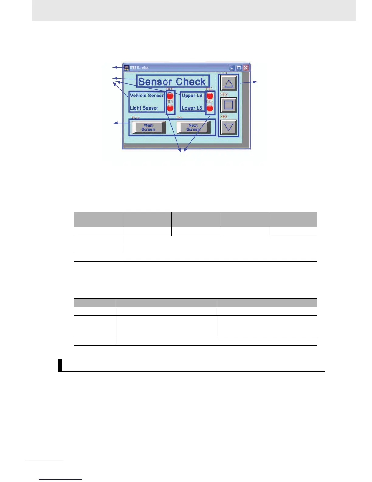
The whole screen is shown below. The creating methods for fixed text and Bit Button components for
[Open], [Stop] and [Close] garage door operations are the same as that of [1 Wait].
a Screen b Fixed Texts c Bit Lamp d Function Keys e Bit Button components
z Bit Lamp Components
The states of the vehicle sensor, light sensor, upper LS and lower LS are shown by the lamp.
The property settings for the Bit Lamp are:
z Function Key Components
These are used for switching to [1 Wait] and [7 Check 2] screens.
The property settings of the Function Key components are:
The [7 Check 2] screen will appear after the screen-switching button on [6 Check 1] or
[8 Check 3] screen is pressed.
Configure functions below:
• Fixed text indicating the garage door state.
• Bit Lamp components activating relevant lamp to check operations when the [OPEN], [STOP] or
[CLOSE] Function Key turns ON.
• Function Key component, a button for switching to [6 Check 1] and [8 Check 3] screens.
• Bit Button components, allocated to [Open], [Stop] and [Close] garage door operations respectively.
Corresponding
Name
Vehicle Sensor Light Sensor Upper LS Lower LS
Read Address CIO_bit0.03 CIO_bit0.04 CIO_bit0.05 CIO_bit0.06
Type Normal
Label Do not use
Graphics Use the vector graphic: Lamp2State1-00.vg
Screen Name Wait Screen Next Screen
Function Key Change screen [1 Wait] Change screen [7 Check 2]
Label Transport font:
0: Wait Screen
1: Wait Screen
Transport font:
0: Next Screen
1: Next Screen
Graphics Use the vector graphic: CTRL_BAR001.vg
[7 Check 2]
 Loading...


