'
Connec-
Signal name Abbrevi-
Signal direction
tor pin #
ation
Input Output
1 Frame ground FG --- ---
2 Send data SD (TXD) --- Yes
3 Receive data RD (RXD) Yes ---
4 Request to send RS (RTS) --- Yes
5 Clear to send CS (CTS) Yes ---
7 Signal ground SG (GND) --- ---
14 Optical connector +5V +5 V --- ---
Note 1. FG is not connected internally in the PT.
2. Unlisted pins are not used.
Refer to
Appendix B RS-232C/RS-422 Connector Cables
for details on cable
parts and wiring connections.
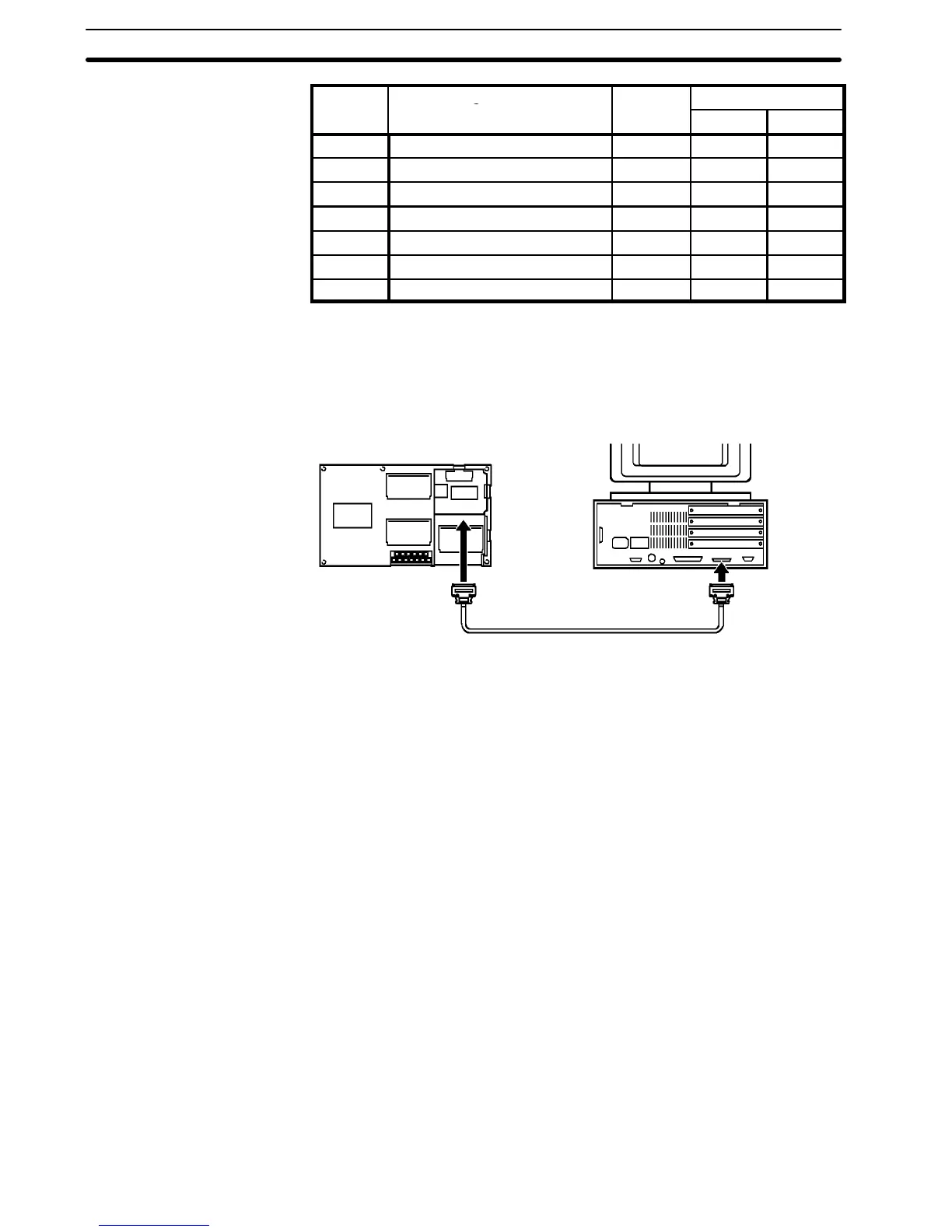
Connecting to the Host Computer
NT600M
25-pin connector
RS-232C Interface Unit
Host Interface
connector (RS-232C,
25-pin type)
PT
rear face
25-pin
connector
RS-232C cable
Note Turn off the PT power supply when connecting or disconnecting connectors.
InadditiontoRS-232Cthe following twoother connectionmethods areavailable
to connect the PT tohost computer.Refer to
Appendix C Connections Using Dif-
ferent Cable Types
for more information on these connection methods.
RS-422
Use RS-422 connections if the PT is more than 15 m from the host computer.
Communication is possible up to 500 m through a multicore shielded cable.
Optical-fiber
Optical-fiber cable connections are used in situations where unstable commu-
nication occurs because of noise problems. Communication is possible up to
500 m through optical-fiber cable.
Connection Using RS-422
or Optical-fiber Cable
Section 2-3