KM1 KM2
S2
S3
S2
S1
M1
KM1
KM2
0V
E1
0VDC (Brown)
Standby input (Violet)
Zone Select 1 (Orange/White)
Zone Select 2 (Orange/Black)
Zone Select 3 (Gray)
Start (Black)
Auxiliary output(Blue)
Warning output (Red/Black)
EDM (Brown/White)
Safety output B (Yellow)
Safety output A
(Red)
* 2
*3
*3
* 1
+24V
Basic connection (with single OS32C unit)
Category 3, Performance Level d(ISO13849-1)
S1 : Start Input
S2 : Zone Select Switch
S3 : Standby Switch
KM1, KM2: Forced guided relay (G7SA)
or magnetic contactor
M1 : 3-Phase Motor
E1 : 24 VDC Power
Functional Earth (Green)
24VDC (White)
OS32C Configuration
- Start/Restart Interlock
Zone Select 4 (Pink)
Zone Select 5 (White/Black)
S2
*3
S2
*3
S2
*3
*3
*3
*3
Zone Select 6 (Tan)
Zone Select 7 (Orange)
Zone Select 8 (Blue/White)
S2
S2
S2
*1. If the External Device Monitoring is not used, connect brown/white wires to 0V,
and then disable the External Device Monitoring with the configuration software.
*2.
The Start Input must be a Normally Closed switch.
*3. For zone select switch setting, see Zone Set Input Selection. When using only one zone,
no connection is needed for the zone select inputs.
KM1
KM2
PE
- External Device Monitoring
Enabled
Wiring Connections
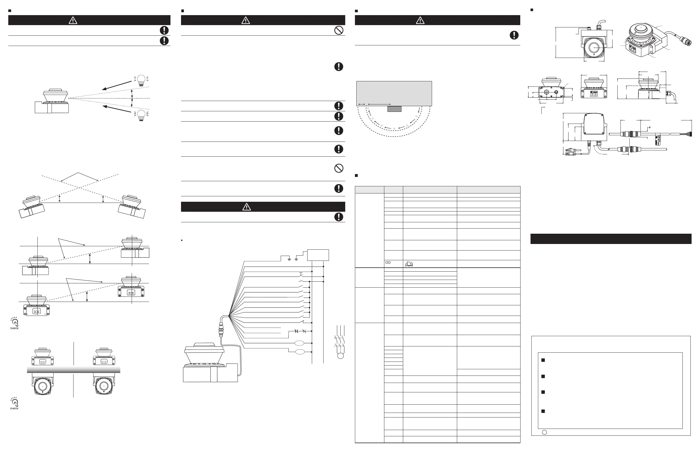
Testing a Horizontal Safety Zone
Top view
Guarded machine
OS32C
Safety Zone
STOP START
Warning Zone
1 m 2 m
If the OS32C is operating in automatic start mode, make sure that the machine
stops and not restart when the test object is in the safety zone. Check its operation
by approach of a test object into a safety zone. It is recommended that this test be
performed after a shift change or 24 hours of operation.
To test the OS32C’s detection capability, guide the test object along the perimeter of the safety detection
zone as shown in the figure below. The hazardous motion of the guarded equipment must stop immediately
(within the pre- determined accepted stop times). While in Automatic Start Mode, the OS32C MUST
remain in the machine stop state throughout the entire test.
To test the OS32C, use a test object with a diameter appropriate for the selected resolution.
(A test object does not come with the OS32C).
Note:
In this example, a semicircle is configured as 2m of
safety zone and 3m of warning zone.
Verify that all indicators and displays are operating properly and correspond to their defined functions of the
OS32C. Inspect the OS32C housing and the exit window for signs of damage or manipulation.
If the OS32C is used in a stationary guarding application, ensure that the safety zone(s) are clearly marked
on the floor. For mobile applications, make sure that the vehicle stops moving within the limits set in the initial
configuration.
If the OS32C fails any of these tests, lock out the guarded equipment and contact the factory supervisor
immediately.
Testing the Safety Area
The OS32C has the status/diagnostic display on the front, which indicates configuration/error status of
the OS32C.
OS32C Status Check
Status Description
Corrective Action
-
88
- -
-
-
-
Normal Operation
Power up indication
Normal operation (guarded machine stop)
Diagnostic
Code
- - blinking at
1 Hz
01
Standby mode (guarded machine stop)
Interlock state (waiting for start input)
Configuration mode (guarded machine stop)
02
80
Window contamination indication
(guarded machine stop)
70
Incorrect number of active zone inputs
(guarded machine stop)
The window is dirty or scratched, clean or
replace as necessary
83
Window condensation indication
(guarded machine stop)
Condensation is detected in the window, wait
for unit to warm up
84
Blinded beams indication (guarded
machine stop)
Check for mutual interference with another scanner
(see mounting considerations on the user manual),
nearby retro-reflectors or strong interfering light
sources.
71
Invalid or undefined zone input
combination but correct number of active
zone inputs (guarded machine stop)
Safety output fault
Safety output fault
Safety output A is short-circuited to 24V
33
32
Safety output B is short-circuited to 24V
34
Safety output A is short-circuited to 0V
35
Safety output B is short-circuited to 0V
30
Check output connection and wiring
40
EDM (external device monitoring)
fault
Check output external device monitoring
connection and wiring.
Check the NC-contact status of the external
device is changing state before the OSSDs
turning ON.
Check the NC-contact status of the external
device is changing state after the OSSDs
turning ON.
Check the OS32Cs output configuration,
connections and wiring.
Check environment for excessive vibration, shock or
electrical noise; check that the window assembly is
undamaged and securely attached. Or consult factory.
Check for mutual interference with another scanner (see
mounting considerations on the user manual), nearby
retro reflectors (<1m) or strong interfering light sources.
Check the environment for electrical noise
sources or interfering light sources. Or consult
factory.
Check environment for excessive vibration or
shock.
Double check current configuration or reset the
scanner back to manufacture default configuration.
Check zone set select input wiring and zone
configuration selection.
Scanner chassis should be grounded to 0 VDC .
The scanner internal temperature exceeds the
operating limit. Add more ventilation.
41
42
43
External device monitoring fault
before OSSD turning ON
External device monitoring fault after
OSSD turning ON
External device monitoring fault during
OS32C power on
50
51
52
53
54
56
57
58
59
60
Other fault
General fault - caused by internal
problem or extreme environmental
condition
Mutual interference
General fault - caused by internal
problem or extreme environmental
condition
Invalid configuration in unit
72
73
74
75
90
Incorrect number of active zone inputs
(hard fault code after diagnostic code 70
above persists for more than 10 minutes)
Invalid or undefined zone set select input
combination, but correct number of active zone
set select inputs.(hard fault code after diagnostic
code 71 persists for more than 10 minutes)
Standby input or zone inputs voltage
too high
Scanner chassis connected to power (24 VDC).
Cycle power on unit and allow to run with diagnostic
code 83, internal generated heat will reduce
condensation.
(if possible reduce moisture in the environment)
81
Window condensation (fault code after
diagnostic code 83 persists for more
than 30 minutes)
Internal temperature fault
External device
monitoring fault
Refer to Status/Diagnostic Display
Indication of the OS32C user's manual
82
Window not detected or entire dust
detection surface is dirty or blocked.
Check that the window is properly mounted
and clean the dust detection surface.
Check zone set select input wiring, zone
configuration selection, zone set select input
switching time and zone delay configuration
Check zone set select input wiring, zone
configuration selection, zone set select input
switching time and zone delay configuration
Check zone set select input wiring and zone
configuration selection.
Check zone set select inputs or standby input
wired at more than system power (24 VDC).
Do not connect the OS32C to a power supply with more than 24VDC + 25% /
-30%. Do not supply AC power to the OS32C, this may result in electrical shock.
For the OS32C to meet IEC 61496-1 and UL 508, its DC power supply unit must
satisfy all of the following conditions:
• Within rated line voltage (24 VDC +25% / -30%)
• Complying with EMC directives (industrial environments)
• Double-insulation or reinforced insulation between primary and secondary
circuits
• Automatic return for overcurrent protection
• Output retention time of 20 ms or longer
• Satisfying output characteristics requirements of Class 2 circuit or limited
voltage/current circuit defined in UL508.
• Power supply complying with regulations and standards of EMC and safety
country or a region where OS32C is used. (Example of electrical equipment
in EU, a power supply must comply with EMC directives and the Low Voltage
Directive)
To prevent electrical shock, use double-insulation or reinforced insulation from
hazardous voltage (such as 230 VAC).
Cable extensions must be within the specified lengths, otherwise it may result in a
failure of the safety functions.
To use this product for a category 3 safety system, both safety outputs must be
connected to the safety system. Configuring a safety system with only one safety
output may result in serious injuries due to output circuit fault and a failure of the
machine to stop.
Protection of Cable at Installation:
Care should be taken when installing the OS32C cable. The cable must be
properly routed and secured to ensure that damage does not occur.
Functional Earth:
The OS32C system requires a functional earth connection.
Do not connect Functional Earth to a positive ground system. If it is connected to
positive ground, the guarded machine to be controlled may NOT stop, resulting in
severe operator injury.
Signal Connector Isolation:
The connectors used during installation must provide sufficient signal separation
in order to prevent a short circuit condition of the input power and system signals.
OSTI P/N 99863-0020 Rev.H
Omron Companies shall not be responsible for conformity with any standards,
codes or regulations which apply to the combination of the Product in the
Buyer’s application or use of the Product. At Buyer’s request, Omron will
provide applicable third party certification documents identifying ratings and
limitations of use which apply to the Product. This information by itself is not
sufficient for a complete determination of the suitability of the Product in
combination with the end product, machine, system, or other application or
use. Buyer shall be solely responsible for determining appropriateness of the
particular Product with respect to Buyer’s application, product or system.
Buyer shall take application responsibility in all cases.
NEVER USE THE PRODUCT FOR AN APPLICATION INVOLVING SERIOUS
RISK TO LIFE OR PROPERTY WITHOUT ENSURING THAT THE SYSTEM
AS A WHOLE HAS BEEN DESIGNED TO ADDRESS THE RISKS, AND THAT
THE OMRON PRODUCT(S) IS PROPERLY RATED AND INSTALLED FOR
THE INTENDED USE WITHIN THE OVERALL EQUIPMENT OR SYSTEM.
See also Product catalog for Warranty and Limitation of Liability.
When wiring the OS32C to external devices, make sure to follow the color and
coding schemes per EN 60204-1.
Operation of the OS32C may be affected by light in the environment, such as
incandescent light, strobe light and light from a photosensor using infrared light.
Operation of the OS32C may be affected by substances in the environment, such
as fog, smoke, steam and other small particles.
The following considerations should be taken into account when determining the mounting location for
the OS32C. It is possible for ambient light to interfere with normal operation of the OS32C.
Ambient light interference DOES NOT lead to a loss of safety, it may, however, cause false nuisance
stops of the guarded equipment.
Some installations may require that the OS32C be mounted in direct exposure to ambient light. In these
situations you must assure that the separation between the scan plane of the OS32C and the light source
be greater than +/-5°.
Mounting Considerations
Configuring Multiple OS32C Scanners
5° or more
5° or more
Offset Scanning Level by Tilting
Offset Parallel Scanning Levels by Different Installation Height
Separation using a screen
Detection Plane
5°or more
5°or more
Detection Plane
5°or more
Detection Plane
5°or more
Top View
Front View
Screen
The possibility exists that two OS32C may interfere with each other. To avoid this when using
multiple OS32C in the same location, please review the following mounting recommendations.
• Adjust the scanners to offset the scanning plane by tilting the OS32Cs.
• Adjust the scanners to offset the scanning plane by mounting the OS32Cs at different heights.
• Adjust the scanners to different scanning planes and additional sampling scans (response
time) on the OS32Cs.
• Install a barrier to block the direct path of possible signal crossing.
When installing the OS32Cs side by side, it is more effective to set their mounting heights
differently. When adjusting the OS32C tilted, it may be more effective to adjust the OS32C
downward depending on the condition of the outside light source (natural light or halogen light).
Use of a screen may increase the effect of reflection depending on its material. Select one with
matte black finish that is resistant to reflection.
Model (OS32C-BP) shown
158.3 [6.24]
Ethernet connector
with M12 cap plug
(cable not shown)
104.3 [4.11]
Top view
90.4 [3.56]
Window
Dust
Detection
Ethernet cable
not shown
I/O cable
I/O block
Sensor head
Isometric view
140.4 [5.53]
100.0 [3.94]
32.8 [1.29]
50.9 [2.01]
Side view
104.5 [4.12]
67.0 [2.64]
Scan plane
133.0 [5.24]
M5x0.8 (x4)
41.4 [1.63]
Mtg holes
57.0 [2.25]
27.7 [1.09]
50.0 [1.97]
6.0 [0.24]
121.0 [4.77]
Mtg holes
Back view
142.7 [5.62]
Front view
Ethernet connector with M12
cap plug (cable not shown)
88.1[3.47]
71.5 [2.82]
71.3 [2.81] (min)
Ethernet
cable
Bottom view
I/O cable
270 (10.63)
Back plate
I/O cable assy
for OS32C-BP
3.0, 10.0, 20.0 or 30.0 meters
30.0 [1.18]OD
Controller cable assy
OS32C Dimensions
102.9 [4.05]
DIMENSIONS: mm [inches]
CAUTION
CAUTION
WARNING
WARNING
Suitability for Use
s
Oct, 2014
D
OMRON ELECTRONICS LLC
2895 Greenspoint Parkway, Suite 200
Hoffman Estates, IL 60169 U.S.A.
Tel: (1) 847-843-7900/Fax: (1) 847-843-7787
OMRON ASIA PACIFIC PTE. LTD.
No. 438A Alexandra Road # 05-05/08 (Lobby 2),
Alexandra Technopark,
Singapore 119967
Tel: (65) 6835-3011/Fax: (65) 6835-2711
OMRON (CHINA) CO., LTD.
Room 2211, Bank of China Tower,
200 Yin Cheng Zhong Road,
PuDong New Area, Shanghai, 200120, China
Tel: (86) 21-5037-2222/Fax: (86) 21-5037-2200
OMRON EUROPE B.V.(Representative and Importer in EU)
Wegalaan 67-69, NL-2132 JD Hoofddorp
THE NETHERLANDS
Tel: (31) 2356-81-300/Fax: (31) 2356-81-388
Shiokoji Horikawa, Shimogyo-ku, KYOTO, 600-8530 JAPAN
OMRON Corporation Industrial Automation Company(Manufacturer)
Contact: www.ia.omron.com
Regional Headquarters
 Loading...