AP1302CSSL00SMGAH−GEVB
www.onsemi.com
4
Table 1. JUMPERS AND HEADERS (continued)
Jumper/Header No. DescriptionPinsJumper/Header Name
P14 +VDDIO_HB0_SENSE
1−2 (Default) Sets Voltage to +1.8 V (Normal Operation)
3−4 Sets Voltage to +2.8 V
5−6 Sets Voltage to +3.3 V
P15 VBLOW Closed (Default) Normal Operation
P16 +VDDIO_HEAD Select
2−3 (Default) When using with the Demo 3 Headboard
1−2 When using with the AP21057 Dual Adapter Board
P17 +VDDIO_HB1_SENSE
1−2 (Default) Sets Voltage to +1.8 V (Normal Operation)
3−4 Sets Voltage to +2.8 V
5−6 Sets Voltage to +3.3 V
P23 SPI Debug
Open (Default) SPI Interface Disabled
1−2, 3−4, 5−6, 7−8 SPI Interface Enabled
P24 SPI_LS_EN
Open (Default) SPI Level-shifter Disabled
1−2 SPI Level-shifter Enabled
SW1 RESET N/A When Pushed, 240 ms Reset Signal will be Sent to
AP1302
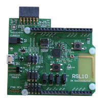
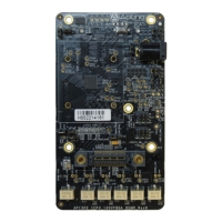
Interfacing to ON Semiconductor Demo 3 Baseboard
The ON Semiconductor Demo 3 baseboard has a similar
52-pin connector which mates with J1 of the headboard.
The four mounting holes secure the baseboard and the
headboard with spacers and screws.
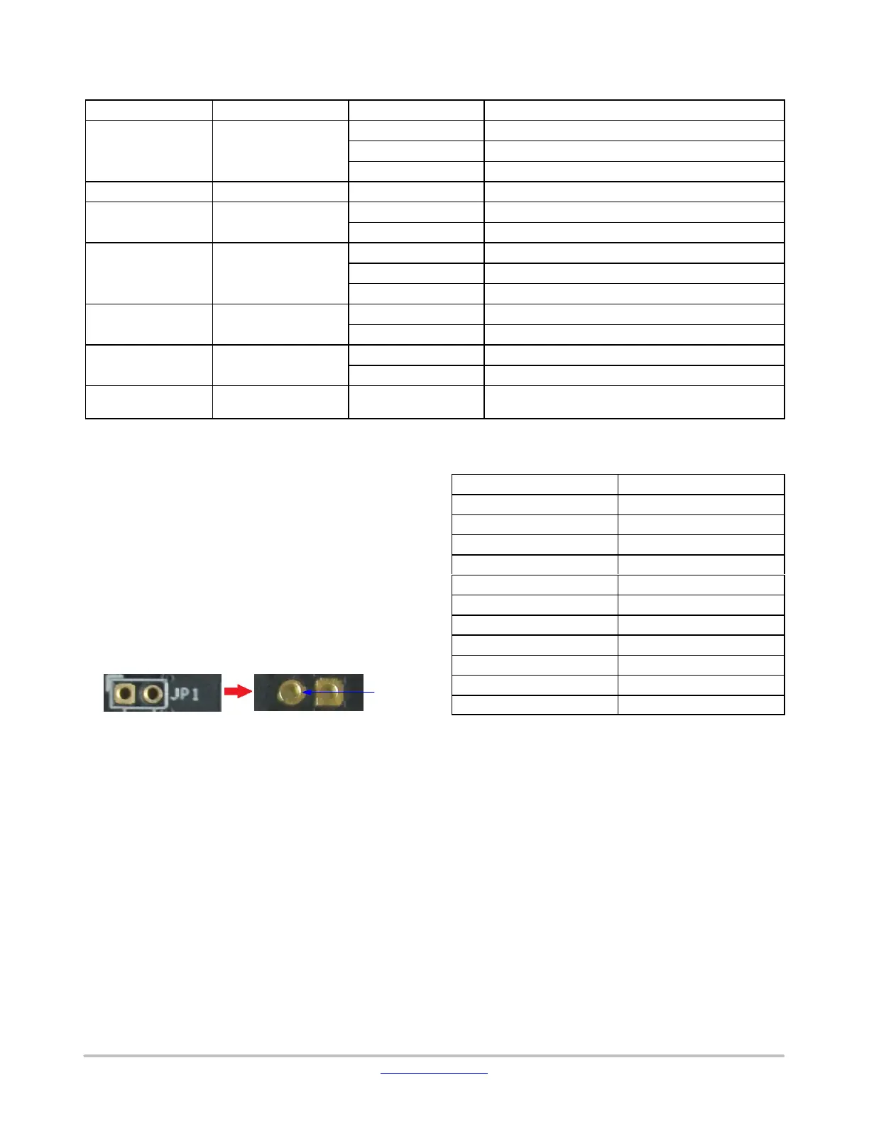
Shorted Jumpers for Power Measurement
Different supplies to the evaluation board are provided by
trace shorted jumper, for any voltage and power
measurements. To conduct current for current measurement
on a given power rail, cut the trace between the two pins of
their respective JP, and insert an ammeter prior to powering
up the system. The figure below shows where the trace to cut
is located.
Figure 7. Top and Bottom View of Shorted Jumper.
The Bottom View Shows the Trace Location to Cut
for Current Measurement
Cut
Here
Table 2. SHORTED JUMPERS FOR POWER
MEASUREMENT
Jumper
Voltage (V)
P1, Pin 1 (+5V0_EXT) 5.0
P1, Pin 2 (+5V0) 5.0
P1, Pin 3 (+5V0_HOST) 5.0
TP12 (+1V2) 1.2
TP14 (+1V8) 1.8
TP15 (+HEAD_1V8) 1.8
TP16 (+3V3) 3.3
TP17 (+2V8_VAA) 2.8
TP19 (+2V8_VDDIO) 2.8
TP21 (+VDDIO_HB0_LS) 1.8/2.8/3.3
TP23 (+VDDIO_HB1_LS) 1.8/2.8/3.3
 Loading...